Frames and fabricated tube assemblies
Include mating ends, holes and locating features needed for assembly. Agree permitted cleanup and fit rather than inferring them from the CAD outline.

STR G · Match profile, gripping, support and the finished tube part.
The STR G menu identifies the two-chuck tube-cutting series. Start with the tube section, outer size, wall thickness, stock length and part drawing. Review how the offered chucks, support, cutting head and handling arrangement work together throughout feeding, rotation, cutting and recovery.
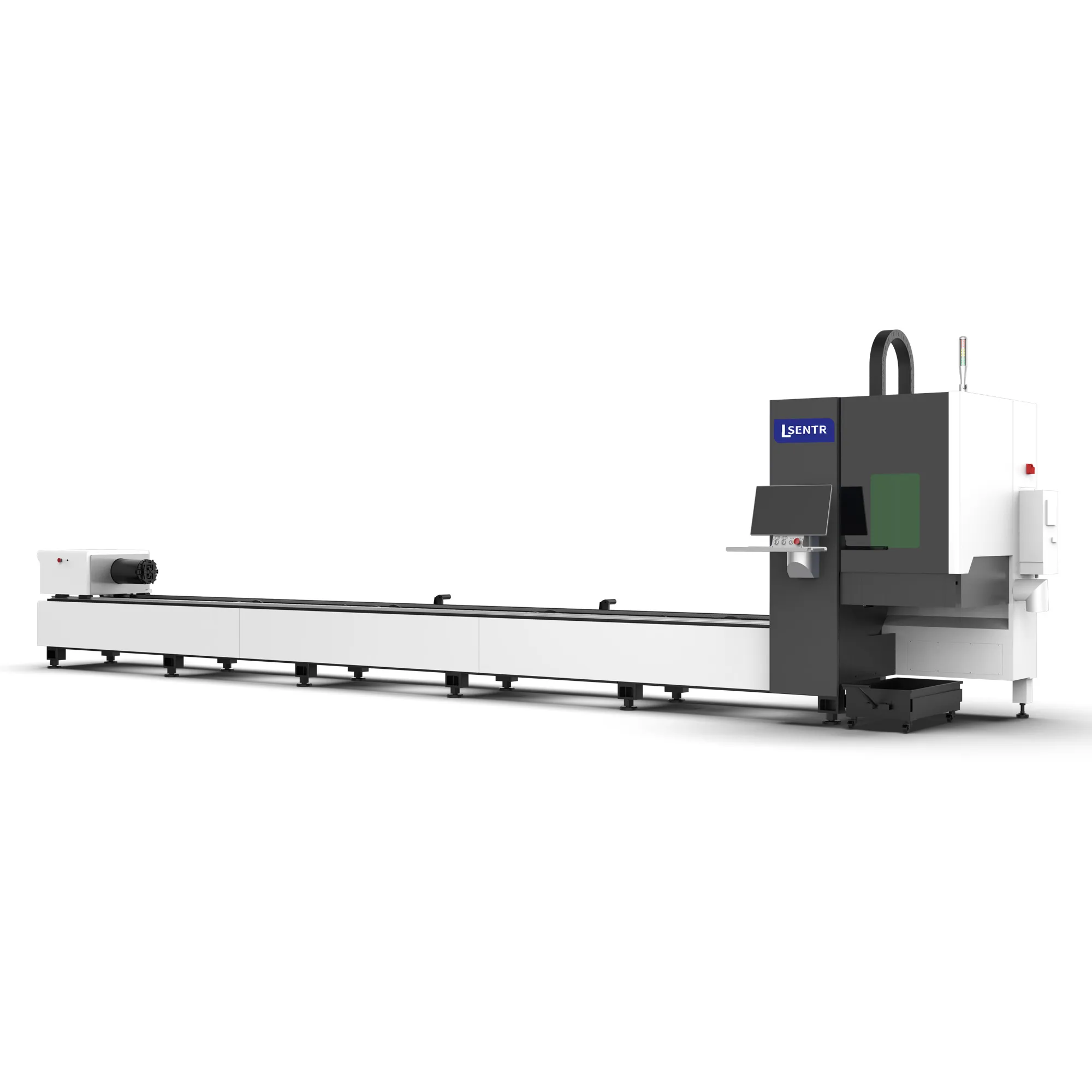
Original G catalogue image with labeled same-image details. The picture does not establish chuck range, bar length, supplied components or tail performance.
A tube and profile configuration reviewed around the actual stock and part.
Include a profile drawing, wall thickness, bar length, weld-seam requirements and a finished-part file. Mark critical holes, face orientation, joints and end profiles.
Tube cutting combines axial positioning with section orientation and the actual support available as material moves through the machine. A round-tube diameter range alone cannot establish how a square section, thin wall, long part or different loading route will behave.
Bring parts with the holes, slots, end profiles and orientation that production needs. Include the locating faces and downstream assembly conditions.
List sections, grades, wall thicknesses, lengths and incoming condition. Review the common work alongside the occasional largest or heaviest tube.
Confirm how the proposed build holds, feeds and supports each section, including when the finished part separates and when only the remnant remains.
Section, outer size, wall, grade, length and condition.
Features, end profiles, seam/face orientation and fit.
Chucks, support, laser package and handling.
Repeated parts, remnants, recovery and complete timing.
The STR menu identifies G as the two-chuck type, while the parent tube page describes the information needed for configuration. Request a G-specific technical sheet; the public category does not provide a verified numeric G capacity table.
| Item | Required definition for the offered machine |
|---|---|
| Series / exact build | STR G Two-Chuck; specify ordered model and configuration revision. |
| Tube and profile range | Supported sections, outside dimensions, wall range, corner geometry and rotation clearance. |
| Stock and part lengths | Loading length, finished-part recovery length and restrictions associated with gripping/support. |
| Mass and support | Permissible workpiece conditions, support arrangement and the relevant loading/rotation limits. |
| Chuck package | Chuck/jaw type, gripping range, contact arrangement, setup and any special tooling. |
| Laser and programming | Source, head, gas, profile programming, nesting and included software functions/licenses. |
| Remnant and handling | Clamping sequence, required reserve, part recovery, scrap handling and supplied loading method. |
| Acceptance and supply | Drawings, sample conditions, measurements, site preparation, training and support scope. |
G-series identity and reference image come from STR's public tube catalogue/menu, reviewed 22 October 2026. Numeric diameter, length, mass, speed, power, accuracy and minimum tail are not established by that source. Confirm them for the actual offered configuration.
| Section to review | Information to provide |
|---|---|
| Round tube | Outside diameter, wall thickness, grade, weld/seam information, length and incoming straightness/ovality requirements. |
| Square or rectangular tube | Both outside dimensions, wall, corner geometry, seam position and the face used as a datum. |
| Oval or other closed section | Complete section drawing, dimensional variation, gripping surfaces and rotation/support needs. |
| Open or special profile | Full profile and part drawings for explicit jaw, support, programming and process-access review. |
| Different stock lots | Dimensional variation, surface/film condition, weld bead, straightness and material identification. |
A section that fits between the jaws may still need more room while rotating or passing supports and the cutting unit. Confirm the full working envelope and process access; do not convert a round-tube limit directly into a square-side limit.
These are application-review categories, not a promise that the standard G package processes every listed section. Identify any required special jaws, support, programming or cutting options in the offer.
Confirm the actual chuck arrangement, movement and working sequence. Review how the stock remains located and supported from its initial grip through the final usable section.
The catalogue rendering cannot establish chuck travel, jaw options, coordinated motion, support actuation or a minimum remaining length.
Discuss gripping stability and permitted marking/deformation with the actual section. Use the supplier's specified setup rather than assuming one gripping condition suits every wall thickness.
Give length, mass and incoming condition. Confirm support locations and how the offered arrangement follows the stock through feeding and rotation.
Identify which face or seam controls the drawing. Review initial orientation, rotational indexing and how those references are preserved through the job.
Review support and recovery when a part separates. Finished-part length and shape can impose different handling needs from the original bar.
For welded stock, seam location can matter to cut continuity, appearance and downstream operations. Mark the required relationship between the seam, the section faces and the programmed features instead of leaving orientation implicit.
Specify whether a hole, notch or joint may cross the seam and which face is controlled. Use the buyer's drawing and material requirements to define the result.
Include representative seam conditions in the trial. Nominal wall thickness may not describe the local cutting condition at a pronounced bead.
Identify cosmetic faces and surfaces used in assembly. Record the permitted seam location and handling marks before comparing samples.
Confirm how the proposed package establishes and checks orientation. Automatic seam sensing or adaptive processing is an optional-function question, not a consequence of having two chucks.
Industry background: BLM GROUP's weld-seam discussion explains why seam orientation and local thickness can affect tube processing. Its named detection/control technologies are not evidence of functions supplied on STR G.
Ask how the proposed machine defines and measures its minimum remaining length under the actual sequence. The reserve needed for gripping/clearance and the unused length left after nesting are different quantities. Part length and process allowance can leave considerably more stock than the stated reserve.
Assume a 6000 mm bar, a 20 mm front trim, 950 mm finished parts and a simplified 5 mm process allowance per part. Compare assumed reserved lengths of 200 and 400 mm. None of these inputs is a G specification.
| Assumed input or result | Case P | Case Q |
|---|---|---|
| Reserved remaining length | 200 mm | 400 mm |
| Maximum count in this arithmetic model | 6 parts | 5 parts |
| Finished-part length total | 5700 mm | 4750 mm |
| Actual unused stock after this allocation | 250 mm | 1205 mm |
Count = floor[(stock − front trim − reserve) / (part length + allowance)]. Actual unused stock = stock − front trim − count × (part length + allowance). The 5 mm allowance is invented for this model, not a kerf setting or process recipe. The model omits actual end geometry, shared cuts, defects, orientation, gripping changes and other restrictions. It does not establish a minimum G remnant or zero-waste capability.
Request the actual stock-to-parts nesting plan and residual-length definition for your drawing. Compare accepted part count and useful remnants rather than a tail-length headline alone.
Identify shape, size, position and which face controls the feature. Include near-corner features and the smallest relevant details in the trial.
Submit cut-off, miter, saddle or mating geometry with the required fit. Confirm process access, programming and finishing for that joint.
Define how features relate around the section. Check angular/face alignment and position across the part, not only one isolated hole.
State permitted internal dross/spatter and any surface that must remain usable. Confirm the proposed process and any required internal-protection option through the sample.
Normal contour cutting does not prove a bevel-head configuration, every 3D geometry or a threaded/finished hole. Identify additional operations and options in the proposal.
| Tube material | Trial information to supply |
|---|---|
| Carbon and structural steel | Grade, wall, section, weld bead and scale/rust condition; required edge before welding, coating or machining. |
| Stainless steel | Alloy, surface/film condition, cosmetic faces, seam requirements and the accepted internal/external cut condition. |
| Aluminum alloys | Exact alloy/condition, section and wall. Verify the offered source/head package, gripping and representative cut result. |
| Other alloys or coatings | Material information for explicit cutting and extraction review, rather than inferring suitability from another tube sample. |
Outside size and wall thickness are separate selection inputs. A large thin-wall tube and a smaller thick-wall tube place different demands on gripping and the cutting process; neither can be selected from a diameter label alone.
The G two-chuck identity does not establish manual, semi-automatic or automatic loading. Confirm the method supplied, section-change requirements and finished-part handling for the actual length range.
| Stage | What to review |
|---|---|
| Stock preparation | Bundle or single-bar presentation, material identification, section orientation and incoming condition. |
| Loading and first grip | Required access, tooling/setup, section range and the actual support/transfer method. |
| Cutting and release | Support and sequence as part length, section and remaining stock change. |
| Unloading and sorting | Permissible finished-part lengths, support, cosmetic/handling limits and traceability. |
| Remnant and changeover | Residual stock handling, jaw/support changes, setup checks and program/material records. |
If repeated bar loading dominates the route, discuss semi-loading or fully loading configurations in the tube family review. Automation must match the same profiles and recovery needs; it is not a substitute for application acceptance.
Use an approved drawing and representative stock. Record material, section/wall, seam condition, machine build, jaws/support, laser/head, gas, software/settings and the agreed process sequence.
| Acceptance item | Define and record |
|---|---|
| Part length and end form | Datums, end geometry, cut condition and measurement method after agreed handling/conditioning. |
| Holes and feature positions | Size, spacing, location along the tube and relationship between relevant faces. |
| Angular orientation | Reference face/seam, rotational relation and the required inspection method. |
| Gripping and straightness | Permitted jaw marks, distortion, bow/twist and any assembly or cosmetic requirements. |
| Inside and outside edges | Dross/spatter, corner/seam regions, permitted cleanup and the next operation's requirements. |
| Repeated allocation | First/later parts, end-of-bar behavior, actual offcut, accepted count and any interrupted/reworked pieces. |
| Complete route | Setup, loading, cutting, unloading, sorting, finishing and inspection under the same timing scope. |
Ask for identifiable samples and a report covering the real material and offered build. Machine-axis or chuck-repeatability figures do not substitute for finished-part measurements.
The current G reference image is catalogue evidence, not a tube-cutting sample or production record. No unrelated sheet-metal sample is used here to imply a passed G trial.
Include mating ends, holes and locating features needed for assembly. Agree permitted cleanup and fit rather than inferring them from the CAD outline.
Review feature location on multiple faces, part length and support after release. Confirm any downstream machining or joining that remains.
Specify cosmetic surfaces, seam orientation and handling marks alongside dimensions. Include the actual finish and inspection expectations.
Compare jaw/support changes, orientation, program preparation and material traceability as well as cutting time. Review the complete section range with the offered package.
Plan machine, incoming bars, staging and released parts together. Confirm the complete footprint, transfer and service access with the proposed handling method.
Obtain actual input ratings and cooling/ambient requirements for the source, machine and auxiliaries. Optical output is not the whole installation's electrical demand.
Confirm gas delivery/quality, extraction and collection access for the material/process. Include short offcuts and remnants in the disposal/reuse route.
Review the supplied protective arrangement and documented operating/service access for loading, rotating stock and recovery. The catalogue housing does not establish a protection rating.
Use the same section range, drawings, output and acceptance scope to compare proposals. A different chuck count or loading system changes the sequence; it does not by itself guarantee a particular tail length or accepted output.
Have the tube section and one representative part drawing?
Prepare a G application reviewUse the specified setup, inspection and maintenance procedures. Retain tooling identification and checks relevant to grip, orientation and permitted marking.
Follow supplied lubrication, cleaning and alignment instructions. Review support condition when section, length or cut results change.
Maintain the specified nozzle/optics, gas and cooling conditions. Record contamination, damage and changes in the accepted process result.
Back up supported profile/program data and parameters. Confirm parts, training, software scope and service responsibility in the contract.
Consumable intervals, warranty coverage and response arrangements require the actual manual and agreement. They are not inferred from the series name or catalogue image.
The dated technical proposal should list the ordered model, section/length limits, chucks/jaws, supports, loading/recovery, laser/head/control, software and auxiliaries. Tie the sample report and inspection plan to that build.
Agree site preparation, packing/transport, installation, commissioning, operator/maintenance training, manuals, spare-parts identification and support contacts. Specify lead time, warranty and exclusions in the actual agreement.
This page does not establish a diameter/power range, production rate, minimum remnant, certification, delivery date or universal service promise.
It follows STR's menu reference for the two-chuck tube-cutting series. The exact chuck movement, jaws, support, laser and handling arrangement still need a configuration sheet and application review.
Submit the full section drawing, outside dimensions, wall and material. Confirm gripping, rotation, support and process access for each required section; do not apply a round-diameter limit to every profile.
Request its definition and a trial under the actual clamping/program sequence. Reserved length is not necessarily the final unused stock after nesting. This page provides no confirmed numeric G minimum or zero-waste claim.
Not from the chuck count alone. Confirm the supplied loading/recovery method, compatible sections, changeover and site layout. Discuss G-SA/G-A configurations if the loading requirement calls for a different package.
Only if the offered sensing/control package includes that function. State seam and face-orientation requirements, then confirm the method and result in the trial.
Review the section, jaw contact, support and permitted deformation/marks with STR. Use the supplied setup and test representative stock rather than assuming a universal gripping setting.
Submit the actual geometry. Confirm head/axis arrangement, programming and access; ordinary tube contour cutting does not establish a bevel option or every possible feature.
Send profile and part drawings, material/section/wall, bar and finished-part lengths, seam requirements, output, loading preference and workshop layout/utilities. Include the current route if you need a complete cost comparison.
These links open STR's tube-family overview for configuration discussions; they are not separate published model pages.
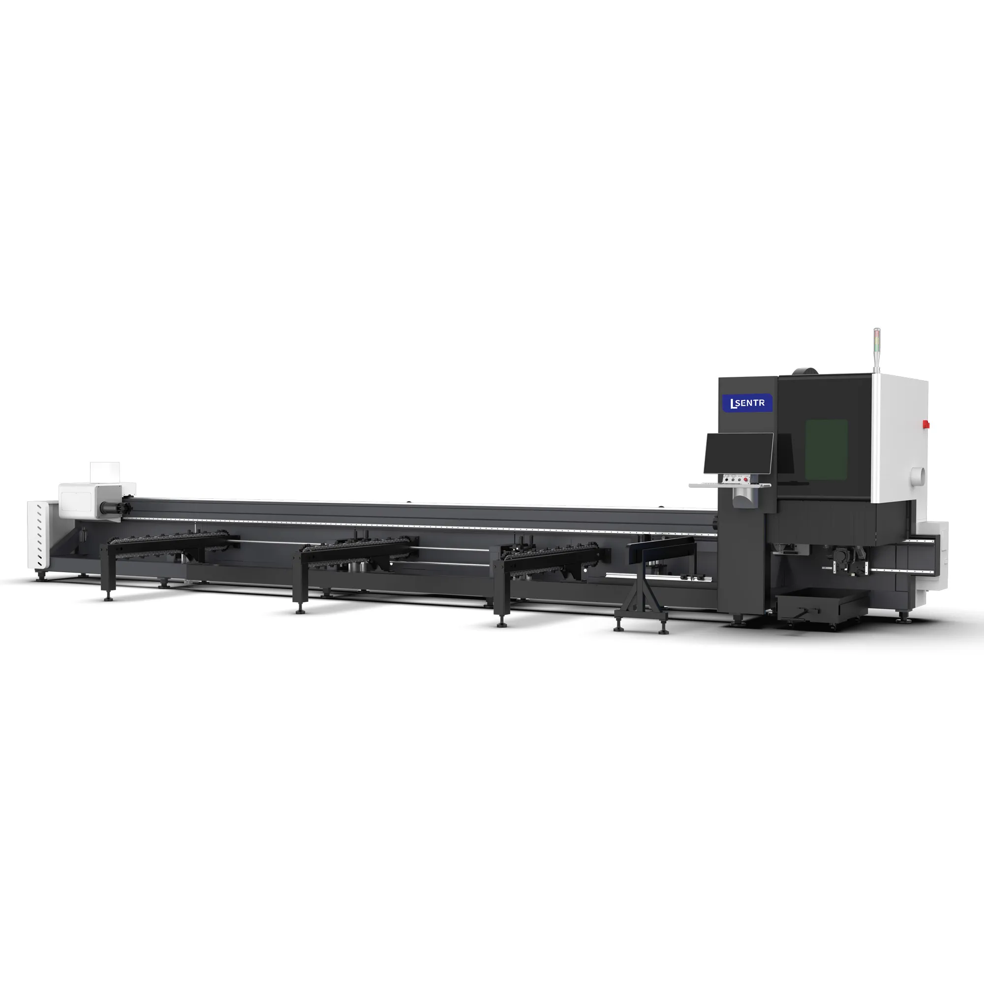
Discuss the supplied loading assistance, compatible sections and changeover requirements.
Discuss semi-loading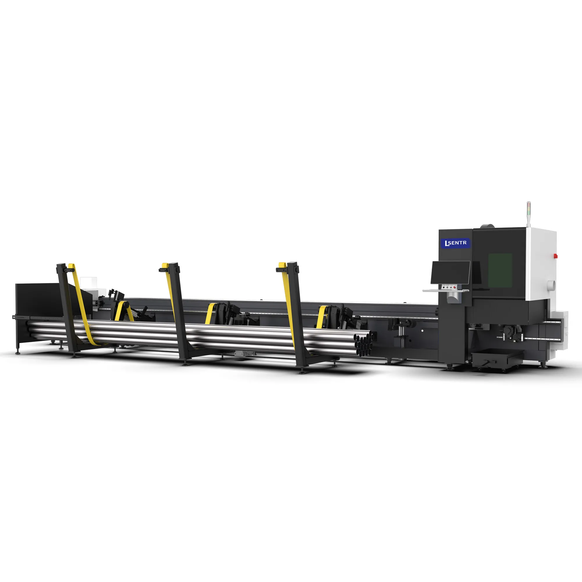
Review the proposed automated handling package, incoming stock and part recovery.
Discuss automatic loadingSubmit the tube and part drawings to compare the actual sequence and accepted result.
Review the tube familySend tube section/outer dimensions, wall thickness, stock and part lengths, material and a representative drawing. Include seam/face orientation, critical features, loading/recovery and workshop utilities.
Prepare and review your requirements summary, then send it through the STR contact page or email. This form does not submit an inquiry.
Discuss your application with STR. We supply industrial laser cutting, welding, cleaning and press brake equipment for metal fabrication.
Tell STR what you need to cut. We will review the application and discuss a suitable configuration.