Repeated short parts
Review whether setup, loading or sorting dominates the route. Inspect the last parts in the nest and account for scrap removal and operator intervention.

STR GT · Coordinate gripping, support and the final section.
For a three-chuck tube laser, the important questions extend beyond the number of grips: how the stock transfers between them, how a long finished part stays supported, and what can be cut from the last usable section. Match the STR GT proposal to your actual tube drawings, lengths, wall thicknesses and production route.
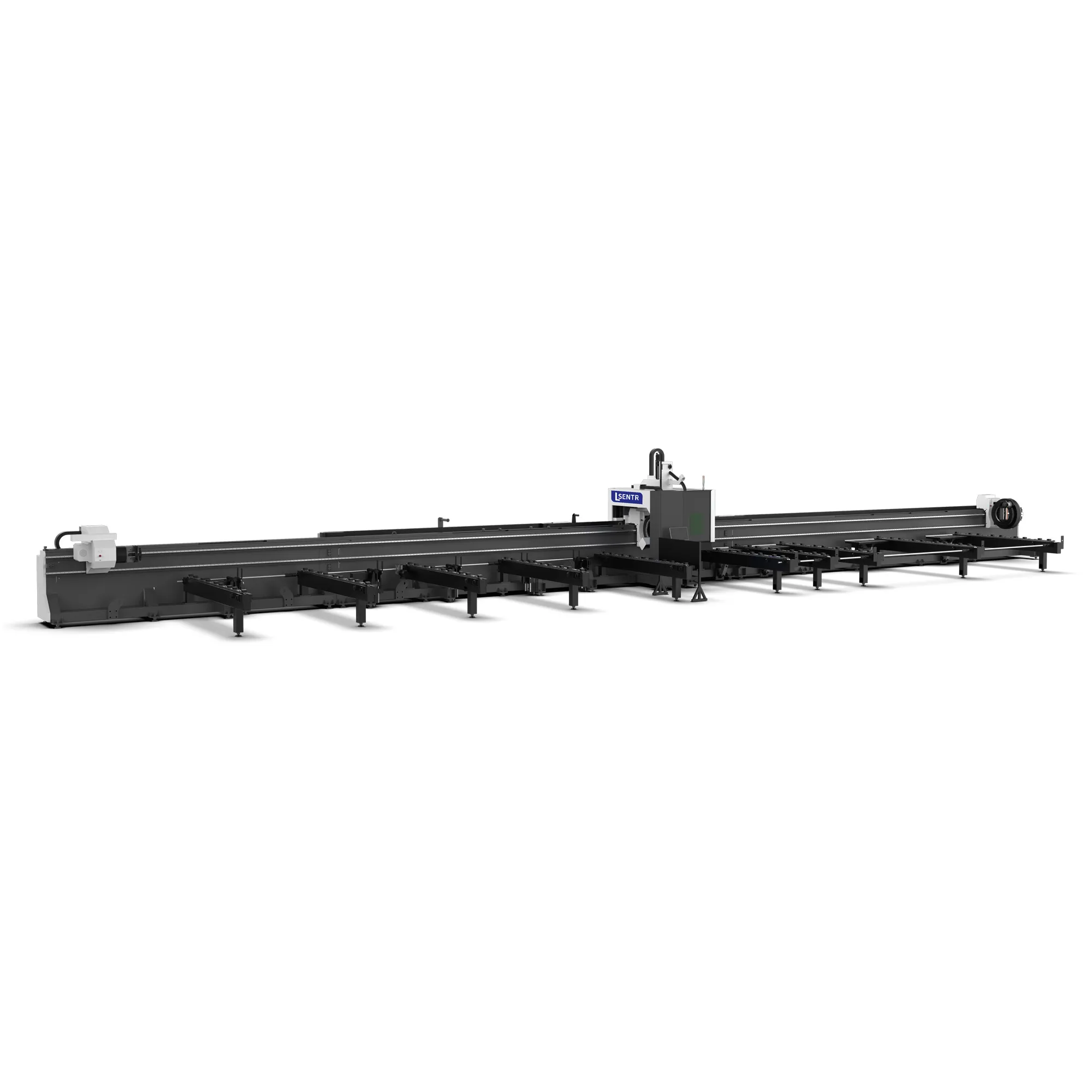
STR GT catalogue image. The detail views enlarge areas of this same image; confirm the supplied chuck movement, support and handling package in the technical proposal.
Select the clamping sequence around the part you need to release.
Send a representative nest and the longest finished part. Mark critical features, gripping-sensitive surfaces and the quality required after any grip transfer.
A three-chuck arrangement offers another grip to coordinate within the cutting sequence. Its value depends on where the grips can move, how location is preserved during a transfer, and whether the outgoing tube or part remains supported as the usable stock becomes shorter.
Review the part's support and recovery path separately from the maximum incoming bar length. A bar that can be loaded does not establish the length that can be recovered to the required quality.
Review grip clearance and the actual final cutting sequence. Establish the remaining-length definition for the proposed jaws, profile and part geometry.
Include hole spacing, face orientation and end features that cross the transfer stage. Check the released part against its datums, rather than judging only a chuck-motion demonstration.
Section, material, wall, length, mass and critical datums.
Locate, transfer, cut the final section and release.
Inspect first, transfer-stage and final pieces.
Include loading, recovery, sorting and setup.
Use a configuration sheet tied to the ordered model and revision. The STR catalogue identifies the GT image with the three-chuck type; numeric capacities and included options need to be established for the actual offered machine.
| Configuration item | What the technical offer should define |
|---|---|
| Model and chuck arrangement | GT model/revision, chuck locations and travel, gripping method, jaw options and transfer sequence. |
| Section and wall range | Qualified shapes and outside dimensions, wall range, corner geometry and rotating envelope. |
| Length and mass | Incoming stock, finished-part recovery, load conditions and support requirements for each relevant section. |
| End-of-bar processing | Required grip/clearance reserve, permitted final operations, remaining-length definition and how the offcut is recovered. |
| Laser and programming | Source/head, gas, control and software functions, licenses, drawing formats and nesting scope. |
| Handling and protection | Loading, support and unloading equipment; operator/service access, guarding and site layout. |
| Acceptance and supply | Test drawings/material, part measurements, full-cycle timing, utilities, commissioning and support responsibilities. |
No numerical GT diameter, length, mass, power, speed, accuracy or minimum-tail range is established by the current catalogue reference. Ask for the GT-specific technical proposal and test conditions.
Map which grip locates the tube at each stage, when another grip establishes contact, and what supports the part as it separates. Ask how the proposed system preserves axial position and face orientation through that change.
The catalogue picture does not establish the control sequence, independently moving axes or transfer accuracy. Review those functions against the actual GT build.
Choose a stage to see what should be demonstrated. This is a process-review aid, not a GT motion simulation.
Identify the initial locating grip, jaw contact and section orientation. Check incoming straightness, wall sensitivity and support before the first cut.
Industry context: Bodor's three-chuck mechanism description illustrates how coordinated gripping can be used in a tube process. Its controls, capacities and zero-tail claims do not describe the STR GT configuration.
Define bar length, mass, section, straightness and initial presentation. Review support positions through feeding and rotation, including non-round sections.
Review the supported length as more material moves to the outgoing side. Include the actual section and part mass; the number of chucks alone does not establish a load rating.
Demonstrate where the finished part is held or supported before its final cut releases it. Agree permitted drop, jaw marks, distortion and handling damage.
Check whether the same recovery route handles the smallest parts and end pieces. Record sorting, scrap access and any operator intervention within the timing scope.
Support needs change with section, length and remaining material. Identify follow-up supports, actuation and recovery functions explicitly in the offer; do not infer them from the rendered bed or supports.
Three chucks do not, by themselves, establish zero tail or an extra finished part from every bar. Separate the reserve required by the grip sequence from the actual unused stock after nesting. Part lengths and allowances can leave the same offcut even when the permitted reserve changes.
Assume an 8000 mm bar, 20 mm front trim and a simplified 4 mm allowance per part. Compare assumed reserves of 300 and 100 mm. These inputs are arithmetic examples, not GT or G performance values.
Blue shows finished-part length only; the remaining track includes trim, allowances and unused stock.
| Arithmetic result | 300 mm reserve | 100 mm reserve |
|---|---|---|
| Finished-part length | 1000 mm | 1000 mm |
| Part count | 7 | 7 |
| Actual unused stock | 952 mm | 952 mm |
Both assumptions permit seven parts. The smaller reserve produces no extra part in this example.
Count = floor[(bar − front trim − reserve) ÷ (part length + allowance)]. Actual unused stock = bar − front trim − count × (part length + allowance). The 4 mm allowance is invented for the example; it is not a kerf or process setting. The model omits joint geometry, shared cuts, stock defects, transfer restrictions and setup losses. It cannot predict an achievable GT minimum tail or production output.
Request a nesting plan and a complete end-of-bar trial for the actual drawings. Compare accepted part count, reusable remnants and intervention time using the same stock and inspection rules.
| Question | G two-chuck review | GT three-chuck review |
|---|---|---|
| How is location maintained? | Review the offered two-chuck sequence through feeding, rotation and final operations. | Additionally demonstrate how location is preserved where a grip transfers or the holding arrangement changes. |
| What happens to a long part? | Check support and recovery for the proposed part length. | Check how the additional grip and offered supports participate in the outgoing-part sequence. |
| How much material becomes useful parts? | Trial the actual nest, reserve and offcut. | Repeat the same nest and record any difference in accepted parts and reusable remaining stock. |
| What is included? | Confirm laser, jaws, support, programming and handling. | Confirm the same scope plus the specified transfer functions; three chucks do not establish automation or a bevel head. |
Choose from the demonstrated result and commercial scope. An additional chuck is not a universal production-rate or quality guarantee. Discuss the G two-chuck configuration alongside the GT proposal.
| Stock or feature | Information needed for the application review |
|---|---|
| Round tube | Outside diameter, wall, grade, length, mass and relevant ovality/straightness. Include weld-bead conditions. |
| Square and rectangular tube | Both outside dimensions, wall and corner geometry; reference face, seam position and rotating clearance. |
| Open or special section | Full section and finished-part drawings for explicit jaw contact, support, control and process-access review. |
| Holes, slots and end joints | Datums, size, position, face relationships and mating geometry; identify which features fall before or after a grip transfer. |
| Visible or thin-wall parts | Permitted jaw marks, deformation, inside-wall spatter and handling damage, alongside dimensional requirements. |
These are review categories, not a qualified GT shape list. Confirm every required section with the offered jaws and software. A round-diameter limit does not define the permitted side length or rotating envelope of a rectangular section.
Send the exact steel, stainless or aluminum grade and wall range. Match the source/head and gas process to the specified edge, inside-wall condition and downstream operations through samples.
Mark the relationship between the weld seam, cosmetic face and critical features. Confirm how orientation is set and checked after a transfer; automatic seam recognition is a function to specify separately.
Review whether setup, loading or sorting dominates the route. Inspect the last parts in the nest and account for scrap removal and operator intervention.
Supply maximum finished-part length and mass, critical end forms and required straightness. Review outgoing support, grip release and recovery access.
Include jaw/support changes, orientation checks, program preparation and the first accepted part after a changeover.
Three chucks do not identify the loading package. Confirm section range, bundle presentation, part lengths, sorting and any remaining manual steps for the offered system.
For loading-specific needs, compare the G-SA and G-A configurations in the tube family. Their catalogue images do not establish compatible GT options.
Use the same material lot, drawings, datums and inspection method when comparing builds. Record the machine revision, jaws/support, laser/head, gas, software and actual sequence.
| Test item | What to inspect or record |
|---|---|
| Initial parts | Length, end shape, hole/slot positions, face orientation and jaw marks against the approved drawing. |
| Features across the transfer | Position and angular relationships on the same part before and after the holding arrangement changes. |
| Longest outgoing part | Supported release, straightness/twist, end quality and recovery without unacceptable distortion or damage. |
| Final usable section | Completed geometry, reserve/clearance conditions, actual offcut, accepted count and interrupted or rejected pieces. |
| Wall and seam regions | Edge condition, inside-wall spatter, corners, local bead and any cleanup needed before assembly or coating. |
| Complete route | Setup, loading, cutting, transfer, recovery, sorting, finishing, inspection and operator intervention under one timing definition. |
A short cutting clip or an axis-repeatability value cannot establish finished-part acceptance through a transfer. Request identifiable samples, measurement records and a video or sequence record covering the entire bar, including the end section.
The GT image shown here is a catalogue reference. No tube sample, production result, certification or measured transfer performance is implied by it.
Include machine travel, incoming bars, released parts, staging, lifting, remnant access and service clearance. Obtain the installation drawing for the ordered build.
Confirm electrical input, cooling, gas quality/delivery, extraction and ambient requirements. Laser optical output does not establish total installation power demand.
Review the documented arrangement for gripping/rotating stock, transfers, cutting and recovery. Housing appearance does not establish a laser protection rating or certification.
Plan material identification, rejected-piece handling, reusable remnants and collection. Include operator access and maintenance downtime in the production plan.
Use the supplied setup, cleaning, inspection and lubrication instructions. Retain tooling identification and checks relevant to seating, marking and transfer consistency.
Inspect contact surfaces and support movement as instructed. When dimensional results change, review stock condition and the complete locating/support chain.
Use specified nozzles and protective optics, with the documented gas and cooling conditions. Set replacement and inspection practices from the actual manual and operating evidence.
Back up programs and approved settings. Identify included licenses, spare-part references, training, remote support and service responsibilities in the agreement.
Compare the machine, chuck/jaw package, supports, loading/recovery, laser/head, software, auxiliaries and installation scope together. Include representative trial material, inspection criteria, documentation and the destination's requirements in the discussion.
Agree packing, transport, site preparation, commissioning, operator/maintenance training, spare parts, warranty scope and delivery schedule in the dated proposal. Compare the cost of accepted parts over the same operating period, including gas, consumables, labor, sorting and finishing.
Have a profile drawing and a representative nest?
Prepare the GT application reviewThe current STR menu identifies the GT catalogue image as the three-chuck type. This page groups that reference as STR GT Three-Chuck. The exact ordered model, layout and included functions should appear in the technical proposal.
No. Establish the actual grip/clearance reserve and permitted end-of-bar sequence for your section and drawings. Nesting can leave more unused stock than that reserve. This page gives no verified numerical GT minimum tail or zero-waste claim.
Compare both around the same parts when grip transfer, long-part support or the end-of-bar sequence matters to your route. Use a full-bar trial, accepted-part measurements and the complete commercial scope to judge the result.
Do not infer finished-part recovery from loading length. Confirm the outgoing support, grip-release sequence, accessible travel and accepted length/mass for the offered build.
Chuck count does not establish any of these options. Specify the required function, compatible section range, sensing/head/control package and acceptance method in the offer.
Measure relevant features and face relationships on a part that spans the transfer stage, using agreed drawing datums. Include first, transfer-stage and final parts; axis or chuck repeatability alone does not establish that result.
Send the complete section, grade, wall, stock/part lengths and mass. Confirm the qualified envelope with the actual jaws, supports, laser/head and software. The catalogue image provides no verified numeric GT capacity table.
Provide profile and part drawings, material/wall, stock and finished-part lengths, mass, a representative nest, critical datums, permitted marks, desired output, loading/recovery preferences and workshop/destination information.
Use the same tube mix and part drawings. These references open the tube family for configuration discussions; dedicated destinations will be bound after their final addresses are confirmed.
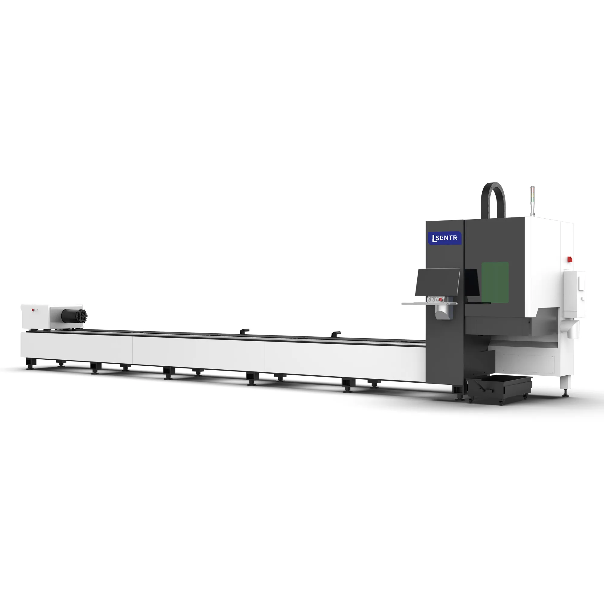
Compare the offered gripping, support and recovery sequence around the same parts.
Discuss G two-chuck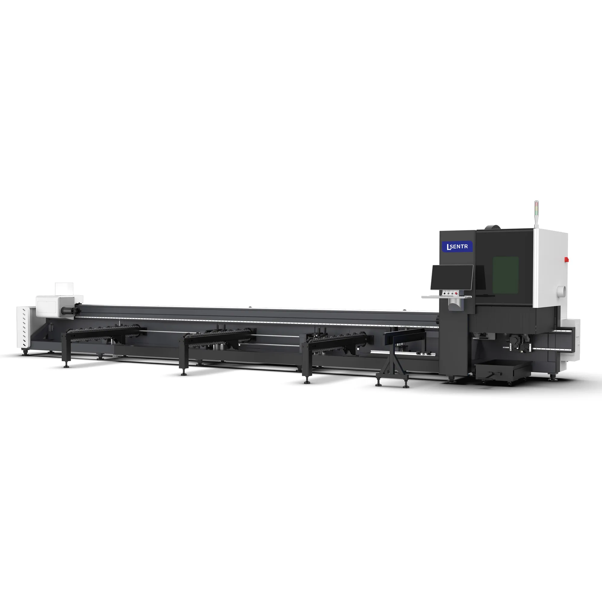
Review loading assistance, section changes and the handling steps that remain.
Discuss loading requirementsSend the actual section, part and nest to compare a suitable chuck and handling package.
Explore the tube familySend the section, wall, stock and part lengths, mass and a representative nest. Mark critical datums, transfer-stage features, recovery needs and the accepted result.
Prepare and review your requirements summary, then send it through the STR contact page or email. This form does not submit an inquiry.
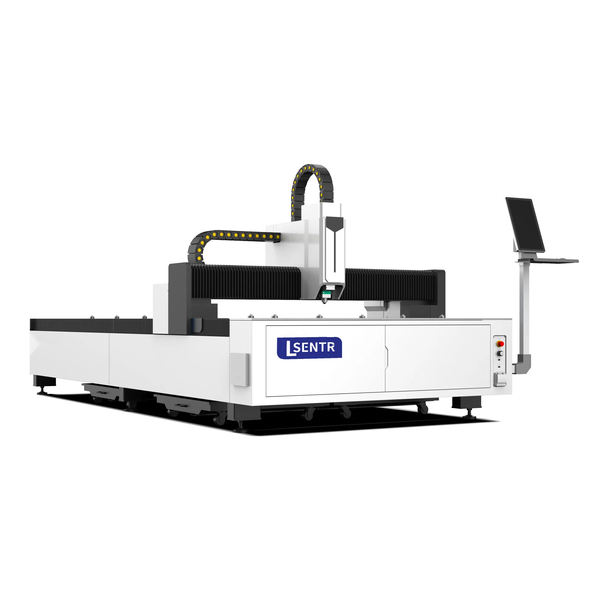
Discuss your application with STR. We supply industrial laser cutting, welding, cleaning and press brake equipment for metal fabrication.
Tell STR what you need to cut. We will review the application and discuss a suitable configuration.