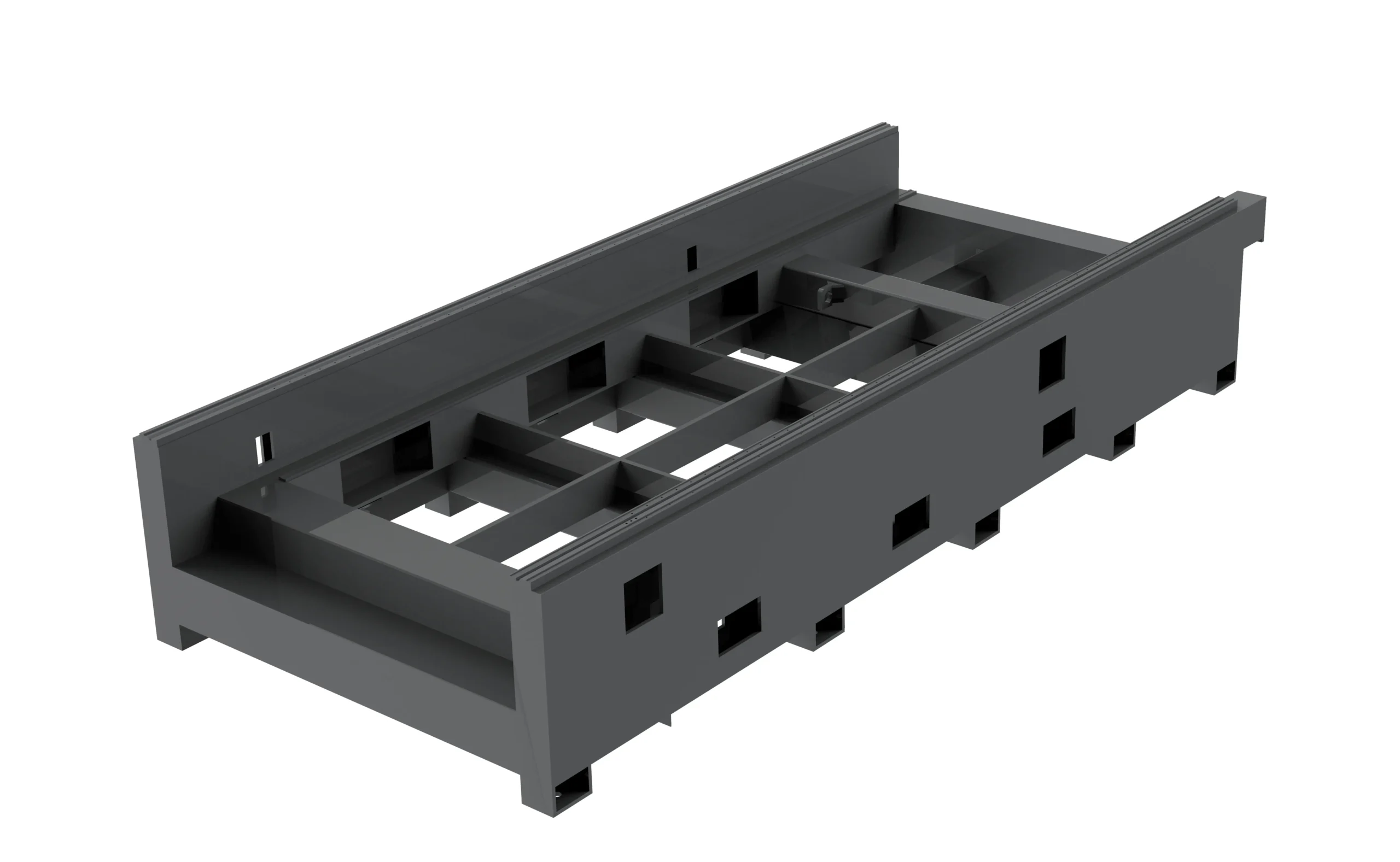
Machine-bed structure
Ask for the offered construction, load assumptions, installation conditions and inspection records. A component illustration does not establish service life or immunity to deformation.

STR AG · Match the motion package to the contours you actually produce.
The STR AG page focuses on motion configuration for sheet-metal cutting. When a job contains frequent repositioning, short contours or repeated direction changes, review how the proposed motion package works with the cutting process. The useful result is a repeatable batch of acceptable parts within a measured production cycle.

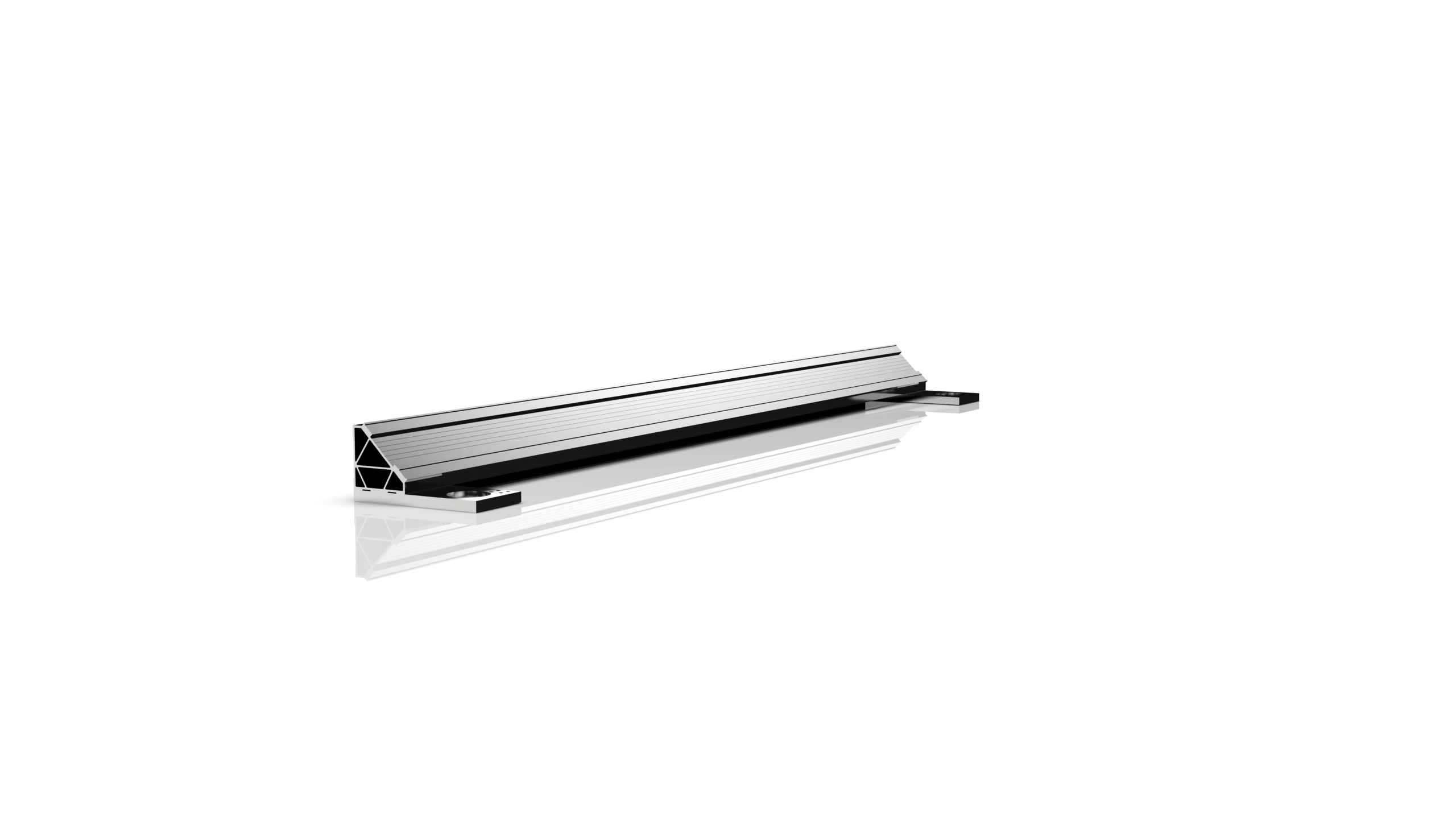
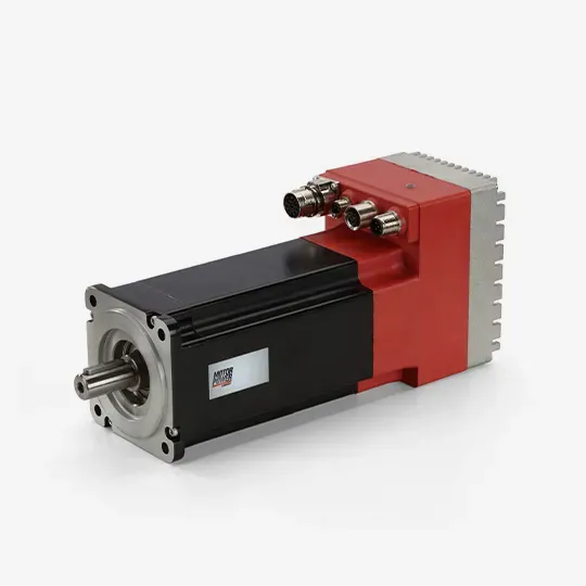

Original AG-page process and component references. They are not multiple angles of one complete machine; the offered build defines the supplied equipment.
Motion configuration for contour-intensive sheet-metal work.
Include hole count, contour mix, material and the current batch cycle. Mark the features that must retain their tolerance and edge condition.
Two nests with similar cut length can place different demands on a machine. Long continuous edges may be governed mainly by the material's cutting process, while many short movements add repeated transitions, piercing and positioning tasks. The AG decision starts by identifying which tasks actually occupy the cycle.
Show the real arrangement of holes, slots, corners and separate parts. The number of entities in a file alone does not describe the controller's continuous motion or the cutting time.
Use a recurring nest and stable material conditions to compare settings. An isolated rapid move cannot establish the output of a shift.
Set the required edge, feature dimensions and support strategy first. A shorter cycle is useful only if the parts still meet those requirements.
Use the same drawing revision, stock and part count.
Agree dimensions, edge condition and any finishing work.
Record cutting, piercing, repositioning and handling.
Check performance across the agreed run, not a selected best move.
This is an application-review method, not a published AG benchmark or guaranteed production gain.
The existing STR3015AG page provides a model reference and working-area reference. Request a dated technical sheet for the exact offered machine before committing to motion performance, component selection or installation requirements.
| Item | Reference or required confirmation |
|---|---|
| Model reference | STR3015AG |
| Published working area | 3050 × 1530 mm; confirm usable travel, blank envelope and the supplied layout. |
| Motion specification | State axis versus simultaneous speed, acceleration/deceleration and applicable load/test conditions. |
| Control profile | Identify how the offered system handles transitions, contour planning and dynamic limits; list included functions. |
| Laser, head and gas | Identify the supplied package and the material/edge requirements used to select it. |
| Part quality | Use drawing-based acceptance, a defined inspection method and a representative trial. |
| Electrical and installation | Confirm the actual electrical supply, auxiliaries, floor/load requirements and complete installation drawing. |
| Supply and support | List components, software/licenses, spares, training, documents and commercial responsibilities. |
* Working-area reference from STR's existing STR3015AG page, reviewed 22 October 2026. The older page contains inconsistent acceleration and power narratives, so numerical speed, acceleration, accuracy and power claims are not adopted here as a confirmed current configuration. Final technical and acceptance documents govern the order.
A speed limit describes how fast a permitted move may become. It does not tell you whether a short move has enough distance to reach that speed, or whether the cutting process permits it.
These describe how quickly velocity changes. On a move that starts and ends slowly, the transitions can occupy most of the distance; increasing the speed limit alone may change little.
Jerk describes how acceleration changes with time. Controlled transitions are part of the motion design, alongside mechanical response and servo control. Do not compare acceleration labels without considering the actual profile.
A curve, corner, narrow web or cutting-quality requirement can impose a different speed limit from an empty straight rapid. Controller behavior and process settings must work together.
General motion background: Beckhoff's jerk-limited acceleration explanation. This is a technical reference, not evidence that STR AG contains a Beckhoff controller or a particular function.
A simple rest-to-rest calculation makes the distinction visible. Assume equal, constant acceleration and deceleration, a straight path and a speed cap. If the path is too short to reach the cap, the ideal velocity profile is triangular rather than a full accelerate–cruise–decelerate profile.
Assume a speed cap of 2 m/s for both profiles. P uses 5 m/s² acceleration; Q uses 10 m/s². These are invented mathematical inputs, not specifications for AG, A or any offered machine.
| Ideal move | Profile P | Profile Q |
|---|---|---|
| Distance needed to reach the cap and stop | 800 mm | 400 mm |
| 40 mm move: peak speed | 0.447 m/s | 0.632 m/s |
| 40 mm move: total motion time | 0.179 s | 0.126 s |
| 1000 mm move: total motion time | 0.900 s | 0.700 s |
With distance L, acceleration a and speed cap v: the threshold distance is v²/a. Below the threshold, peak speed is √(aL) and time is 2√(L/a); at or above it, time is L/v + v/a. This idealized model omits jerk limits, servo following, controller planning, settling, process feed limits and all cutting/piercing/handling tasks. Real continuous contours do not stop at every drawing segment, so the example must not be applied separately to each line in a CAD file.
Use the example to decide what to measure, not to calculate a promised AG cycle. A meaningful comparison needs the real toolpath, process conditions and acceptance result.
Separate the complete cycle into cutting, piercing, non-cutting travel, access/loading and recovery. The tasks that stay unchanged limit the effect of a faster motion package. Also record interruptions, failed parts and any extra finishing required by the compared settings.
Suppose a hypothetical batch contains 30 seconds of repositioning and 170 seconds of all other work. Its total is 200 seconds. If repositioning alone becomes 20 seconds while everything else stays identical, the new total is 190 seconds: a 10-second, or 5%, reduction in total time.
This does not mean AG delivers that change. It shows why a large improvement in one task does not translate into the same percentage change in the full cycle. Any quality loss or added cleanup must also be counted.
Have a recurring nest and current cycle record?
Prepare an AG application reviewDynamic performance belongs to a system. Frame stiffness, moving assemblies, drive/feedback, controller settings, service condition and cutting process all influence the useful result. The photographs below come from the existing AG component gallery; the actual supplied brands, models and options need an agreed bill of materials.
Ask for the offered construction, load assumptions, installation conditions and inspection records. A component illustration does not establish service life or immunity to deformation.
Review the moving structure with its drive and control package. The picture does not establish alloy grade, mass, manufacturing pressure or measured dynamic performance.
Identify the exact motor/drive and feedback arrangement in the offer. Confirm how the configuration is matched and commissioned; a photographed brand is not a complete system specification.
Confirm supported drawing formats, nesting, path planning, included process functions and license scope. A screen illustration is not proof that every displayed option is supplied.

Match the head, focus/height-control arrangement and consumables to the laser package and intended process. Keep head condition and setup consistent in a motion comparison.

Choose around the material and required edge, not an acceleration label. The final proposal should identify the source and the conditions used for the representative cutting trial.
A finished-part requirement is different from a machine-axis positioning figure. When comparing settings, inspect the relevant geometry and process result after the agreed cooling and handling procedure.
| Drawing or process feature | What to inspect |
|---|---|
| Corners and small radii | Contour shape, dimensions and edge condition at transitions, using drawing-based criteria. |
| Dense holes and slots | Feature size, spacing, position, burr/dross and the influence of piercing and local heat. |
| Narrow webs and small parts | Support, flatness, retention, recovery and any allowed tab cleanup. |
| Long edges and repeats | Relevant dimensional checks and edge consistency across the agreed nest and repeated runs. |
| Downstream operation | Fit, bending, joining, coating or machining requirements that determine whether the part is usable. |
Do not compensate for a poor edge by quietly adding extra finishing outside the cycle comparison. Either meet the same acceptance scope, or state the different process route and cost.
Material grade, thickness, surface condition, geometry and assist gas determine the process window. A motion-focused machine description does not establish a universal cutting speed or thickness capacity.
| Material/job | Questions for the trial |
|---|---|
| Carbon steel | Identify grade and scale condition, edge requirements and the process used before painting, welding or machining. |
| Stainless steel | Include alloy, cosmetic face, film condition and the required cut edge; compare the same gas and finish scope. |
| Aluminum alloys | Provide the alloy and surface condition; verify the offered laser/cutting package and representative result. |
| Copper or brass | Seek explicit application review for the exact alloy and package, rather than inferring suitability from steel results. |
| Coated or unusual stock | Identify coatings and supply material information for cutting and extraction review before processing. |
These are general review questions, not an AG capacity chart. This sheet-metal fiber-laser page does not establish a process for wood, acrylic or other nonmetals.
Many internal features combine piercing, short paths and local heat. Bring the actual hole pattern and acceptance requirements rather than estimating time from outer dimensions.
Evaluate corners, slots and locating holes together with part support and sorting. Include any retained tabs and finishing in the batch record.
A nest of dissimilar parts can mix long edges with frequent repositioning. Record the normal mix and order changes so the comparison represents daily work.
Determine whether cutting feed, piercing, material handling or motion transitions govern the cycle. Do not assume a motion upgrade is the main answer when the dominant task lies elsewhere.
Choose a representative production nest and identify the critical features before testing. Record the machine build, material, gas, software/settings and acceptance method so a shorter reported time can be assessed fairly.
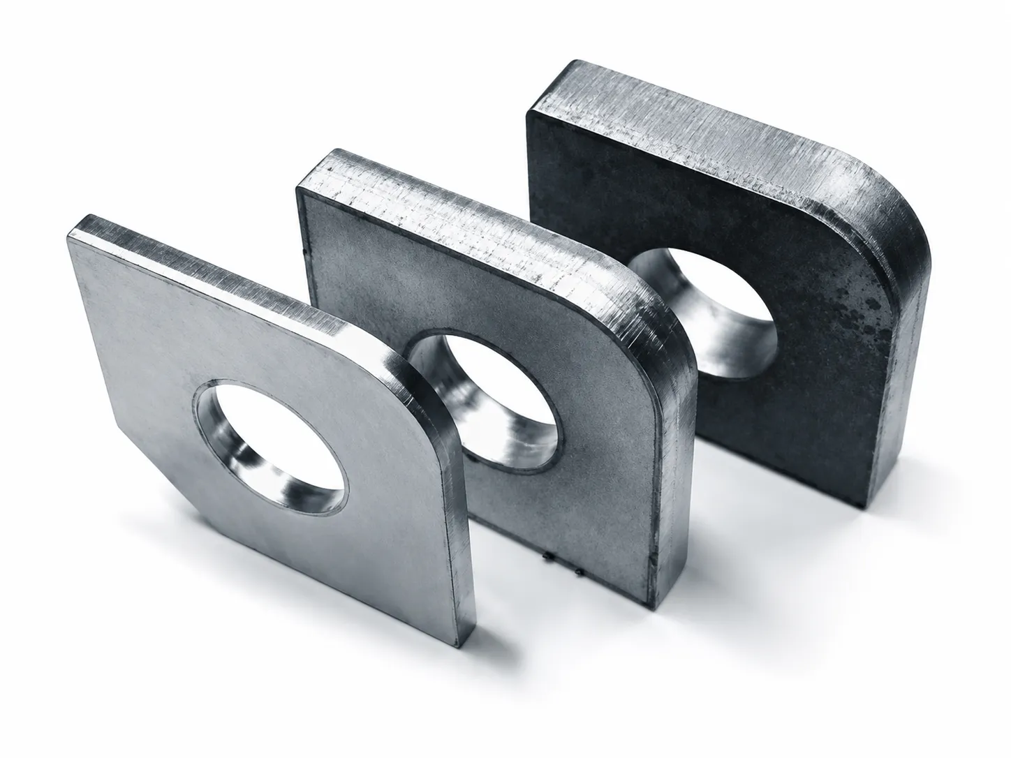
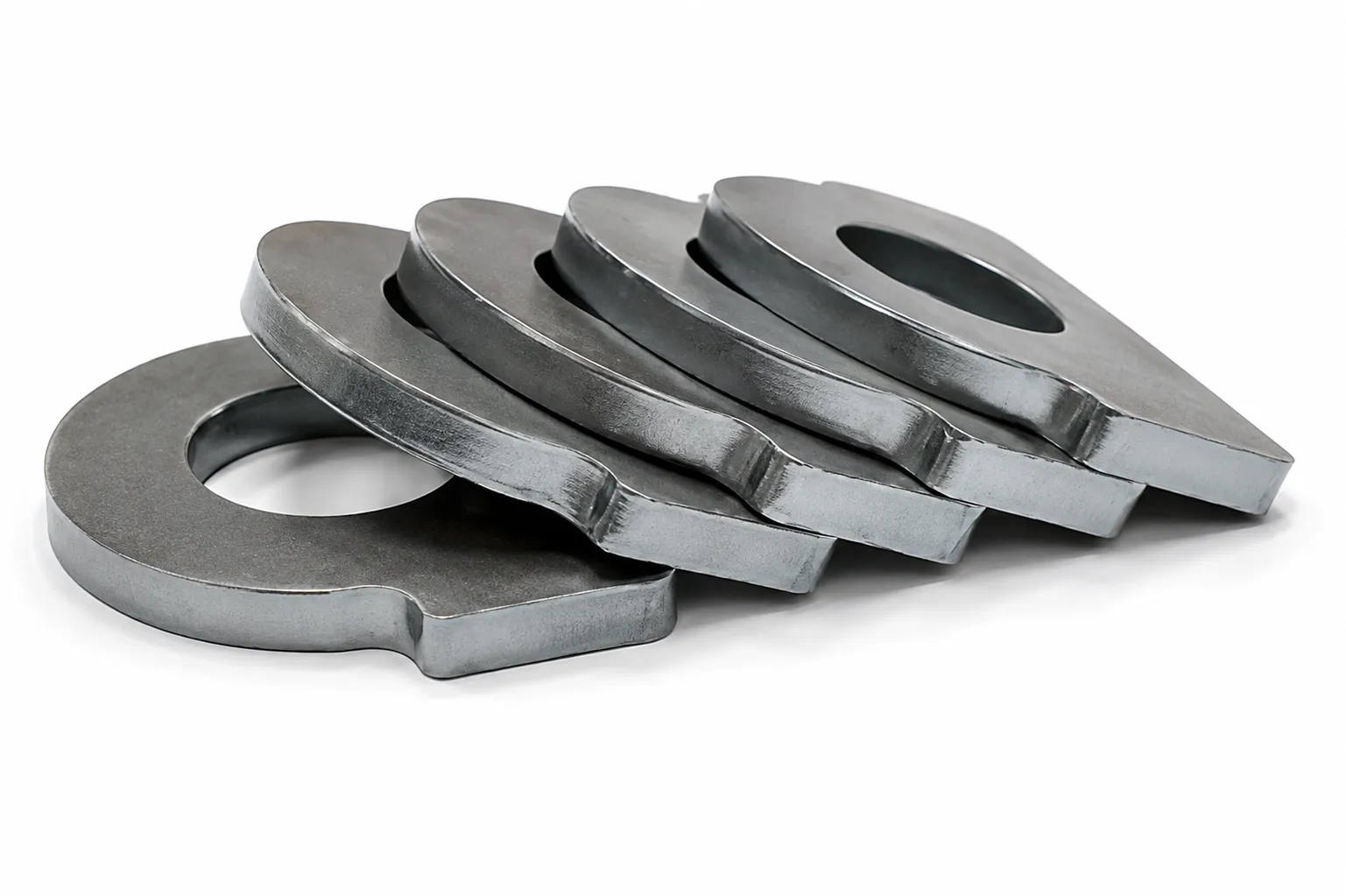
These images illustrate sample presentation. They do not prove AG tolerances, thickness capability, cycle time or a comparative gain.
Fixed inputs: drawing revision, part count, material/grade, thickness, stock size, gas and required result.
Declared differences: machine configuration, motion profile, cutting/piercing settings and any process or tooling change.
Measured outputs: accepted parts, complete-cycle timing, relevant feature measurements, edge observations and repeat-run conditions.
Retain the unedited timing record and identify rejected pieces or interruptions. Different nesting, omitted cleanup or changed acceptance criteria can make nominally similar demonstrations incomparable.
A higher motion capability does not remove the material's process limits. Focus, nozzle condition, gas supply, piercing strategy and feed must suit the job, especially where a toolpath repeatedly changes speed or direction.
Separate the time spent starting internal contours from the time following them. Improving empty travel cannot by itself remove a piercing bottleneck.
The selected gas/process route affects the edge and any later cleaning, painting or joining. Compare the same usable result rather than the same headline speed alone.
Use the required gas quality and supply arrangement for the offered package. Document changes that could alter cutting behavior during the trial.
Ask which process and motion functions are actually included and how they are configured for the job. Do not infer adaptive process control from a generic CNC label.
These choices address different parts of the job. Start with the limiting requirement and compare complete offered packages rather than treating model letters as a simple performance ranking.
| Production requirement | Route to discuss | What must be established |
|---|---|---|
| Frequent transitions and contour-rich work | AG motion configuration | A repeatable improvement on the actual nest while retaining quality. |
| General single-platform sheet work | Standard A configuration | The process, usable sheet area and handling workflow suit the normal workload. |
| Angled edges for a drawing or weld preparation | AP bevel configuration | Required bevel geometry, suitable head/process and final acceptance. |
| Handling between repeated sheets | B or BD exchange-table layout | Outside preparation, exchange envelope, protection and the full sheet cycle. |
| A material/edge task governed by laser capability | Application-specific laser package | Source, head, gas, piercing and sample result—not an acceleration label alone. |
For an angled-edge requirement, review the AP bevel-cutting page. AG motion does not by itself establish bevel capability. For other sheet layouts, start from the fiber laser cutting range.
Follow the supplied operating and maintenance instructions for the installed system. A comparison made with changing consumables, support condition or machine setup can confuse process deterioration with a motion limitation.
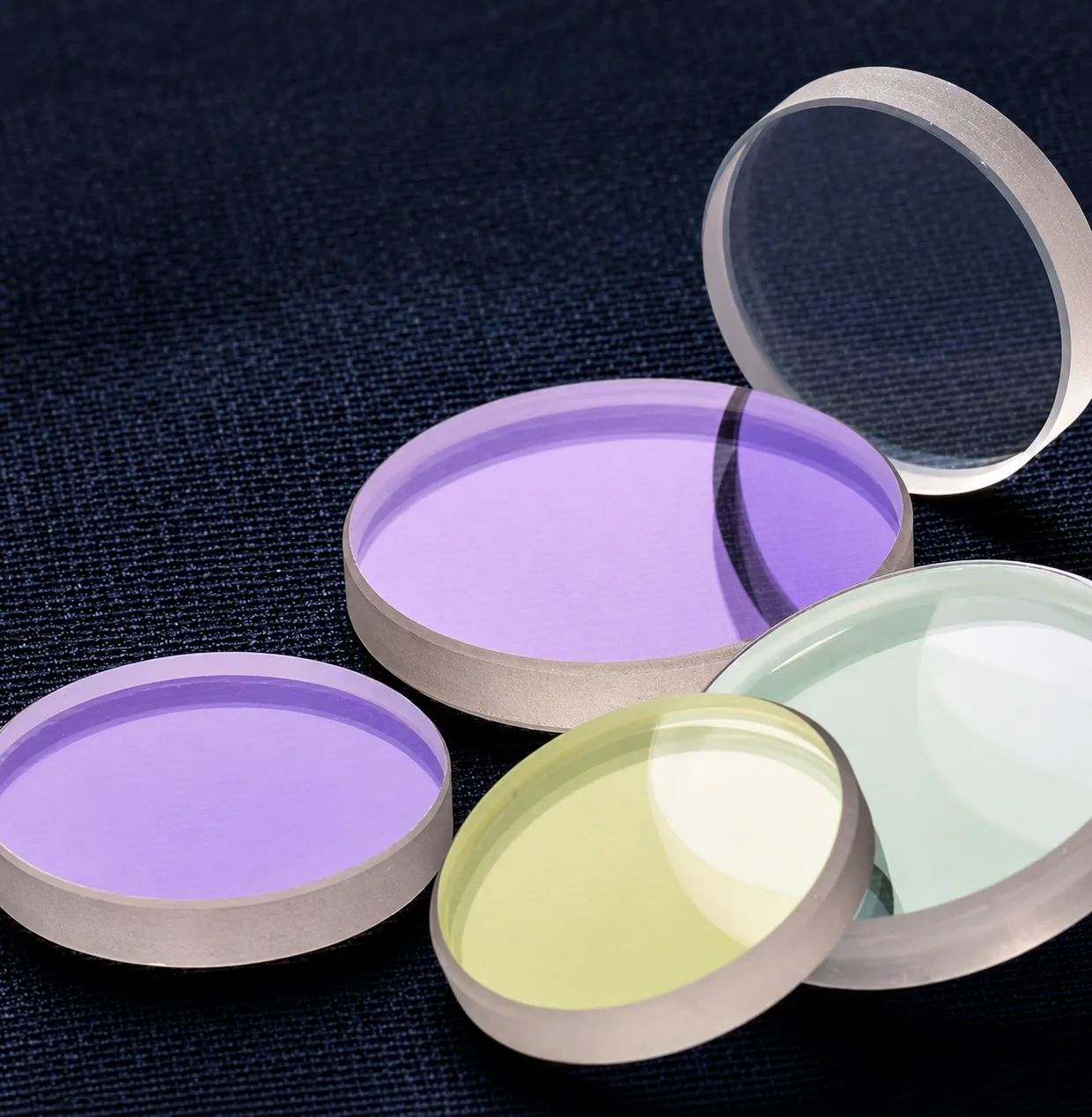
Use the approved parts and handling procedure for the installed head. Record replacements when comparing repeat jobs.
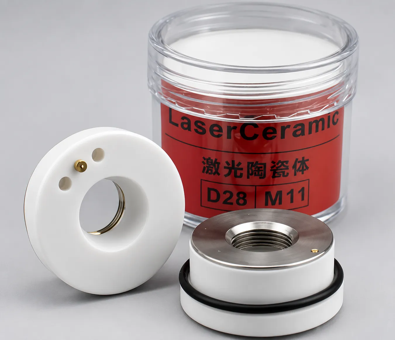
Ask for exact part IDs and inspection instructions. A similar-looking component does not establish compatibility.
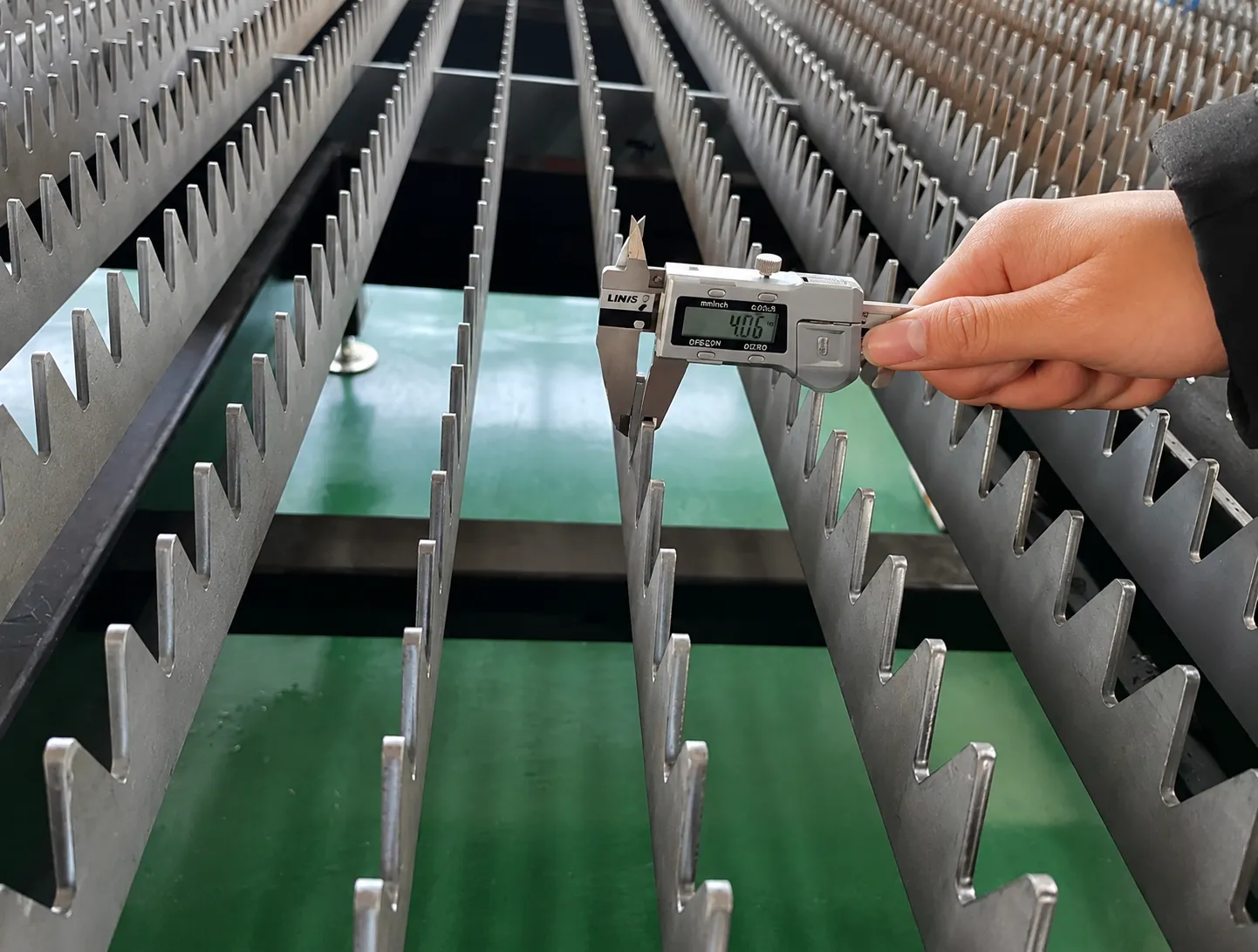
Review the permitted clearing procedure, support condition and collection route so small parts and remnants do not compromise the job.
The consumable pictures are general references, not the AG supply list. Motion-system lubrication, inspection and service intervals must come from the actual equipment instructions.
Agree who may change motion/process settings, how approved configurations are recorded and how to return to a known state. Include drive, feedback, mechanical and process checks in the troubleshooting responsibility without implying a particular diagnostic feature is supplied.
Request the drawing and utility requirements for the complete offered machine. The bed, loading route, auxiliaries, service space and protective arrangements all belong in the layout.
Check foundation/floor requirements, installation and leveling instructions, stock delivery, loading and collection. Define the installed protection and operating access for the offered layout.
Confirm electrical supply, cooling, gas and extraction scope, connection responsibilities and service clearances. Include destination documents, commissioning and training in the written offer.
Do not infer an enclosed layout, automatic loader or a destination safety certification from the AG process photograph. Review the actual supplied system and its documentation.
There is no fixed public price or payback promise in this preview. Use a job-specific proposal and a transparent acceptance test to assess whether the configuration addresses the real bottleneck.
A demonstration using another material, different nesting or relaxed quality criteria is not the same acceptance job. Keep the evidence tied to the machine and configuration being supplied.
It emphasizes the motion package's ability to change velocity within stated conditions. For AG, evaluate the offered configuration with the cutting process and actual nest; a headline acceleration figure does not establish finished-part output.
No. Short moves may not reach it, cutting feed may be process-limited, and piercing or handling may dominate. Measure the full job and preserve the same acceptance result.
Request the current technical sheet for the exact offered build, including axis/simultaneous definitions and test conditions. The older page used inconsistent acceleration descriptions, so this preview does not present one of those numbers as a confirmed specification.
No. Profiles P and Q use invented constant-acceleration inputs to explain short-move behavior. They omit actual controller, mechanical and cutting-process effects and do not predict AG production time.
No. Actual path planning and continuous contouring can pass through segments differently, subject to quality and dynamic limits. Use the real program and measured cycle rather than summing the simplified example for every segment.
No. Finished-part quality depends on the complete system, material, process and inspection conditions. Set drawing-based acceptance and inspect the relevant features during the agreed trial.
No. Motion configuration and angled-edge processing answer different requirements. A bevel job needs the appropriate head/process and geometry review; AG's motion focus does not establish bevel capability.
The images are references published on the existing AG page. The final offer must name the source, head, controller, drive/motor, included functions and compatible parts actually supplied.
Do not assume that. Identify the actual AG laser/head package, material and required edge, then agree a representative cutting trial. Another model's capability is not an AG specification.
Send the current drawing or nest, material/grade, thickness, stock size, part count, critical features, finish requirements and available cycle records. Add the destination, workshop utilities and required supply scope.
Motion, the cutting package and sheet handling need to fit the same job.
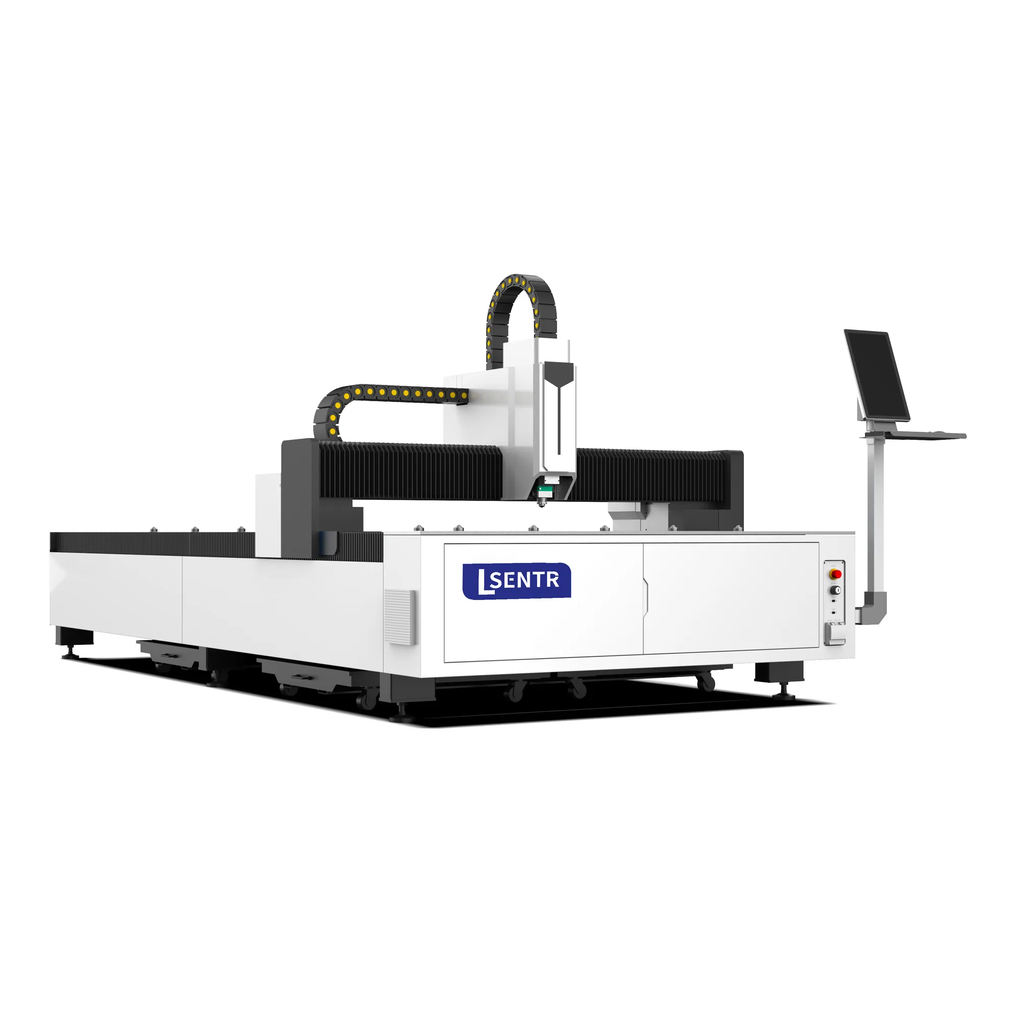
Review a single open worktable and a configuration for the normal material and job.
View standard A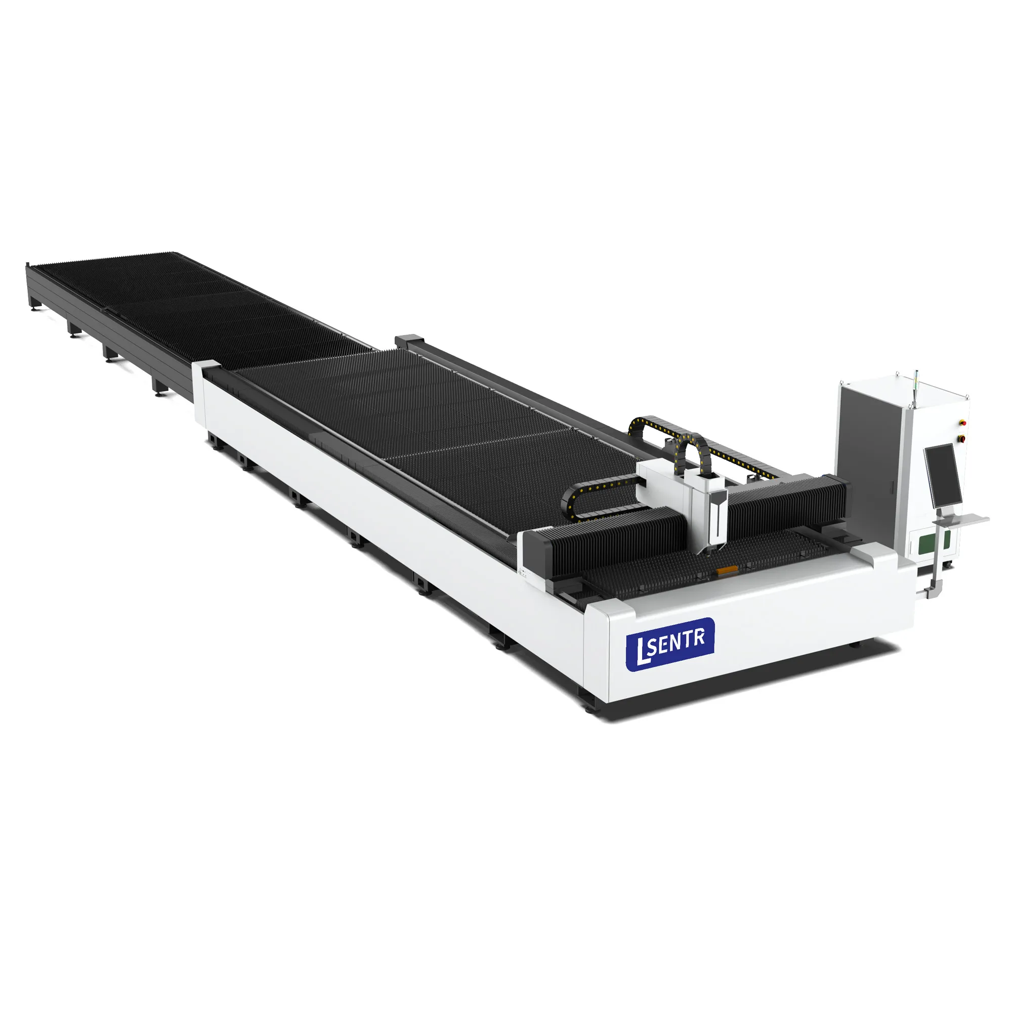
Review outside preparation, exchange travel and the complete sheet-handling route.
View the B layout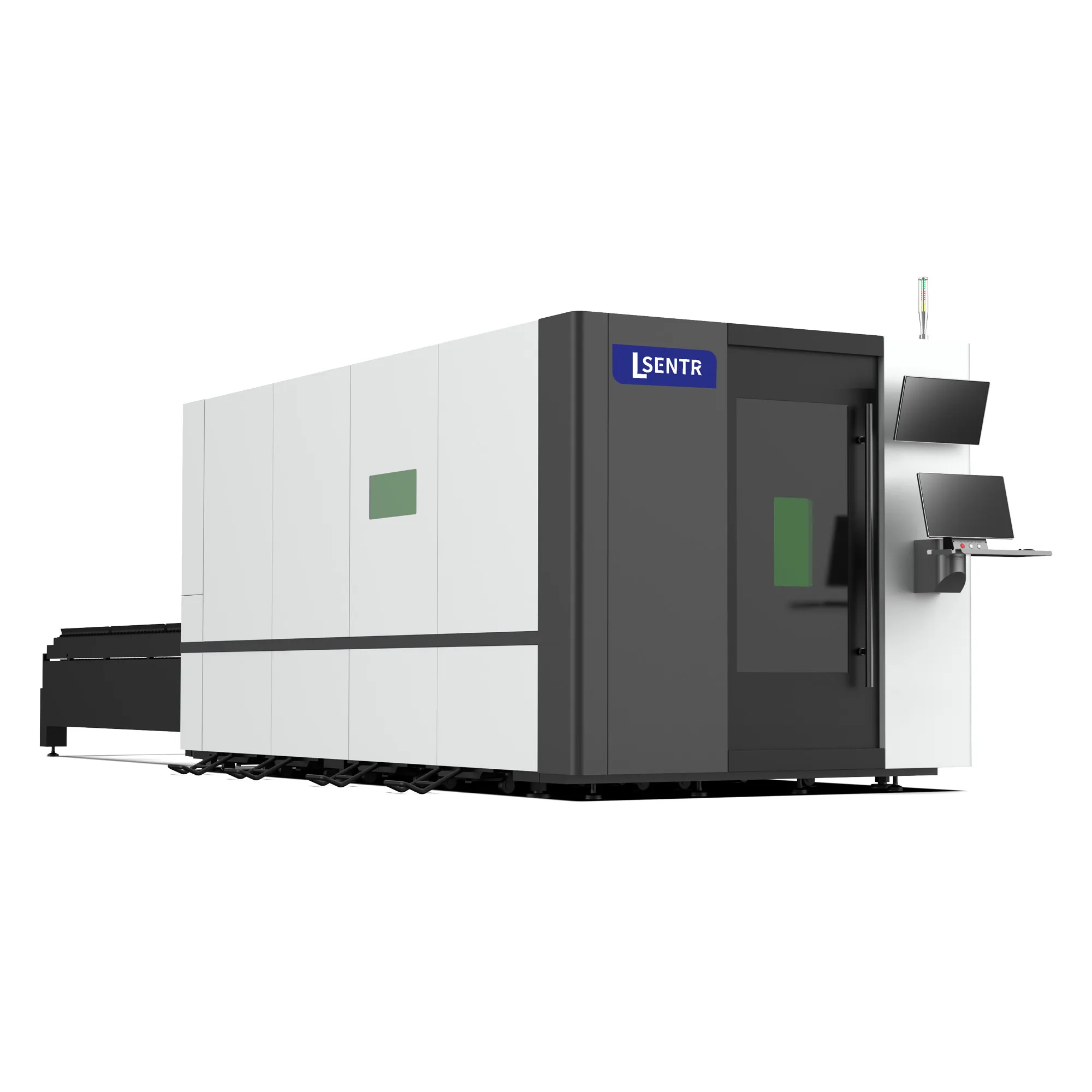
Compare external handling with an enclosed cutting position and its supplied access package.
View the BD layoutSend a representative nest and separate the cutting, piercing, repositioning and handling tasks. Mark the drawing features and edge conditions that must be preserved when comparing motion configurations.
Prepare and review your requirements summary, then send it through the STR contact page or email. This form does not submit an inquiry.
Discuss your application with STR. We supply industrial laser cutting, welding, cleaning and press brake equipment for metal fabrication.
Tell STR what you need to cut. We will review the application and discuss a suitable configuration.