
Welded machine bed
Supports the sheet and motion assembly. Check the construction, permitted sheet load and machine layout for the proposed build.

STR A · Open-table sheet metal cutting
The STR A is an open-type, single table fiber laser cutting machine for flat metal sheets. Produce panels, brackets and enclosure blanks with a configuration matched to your material, thickness and daily workload.
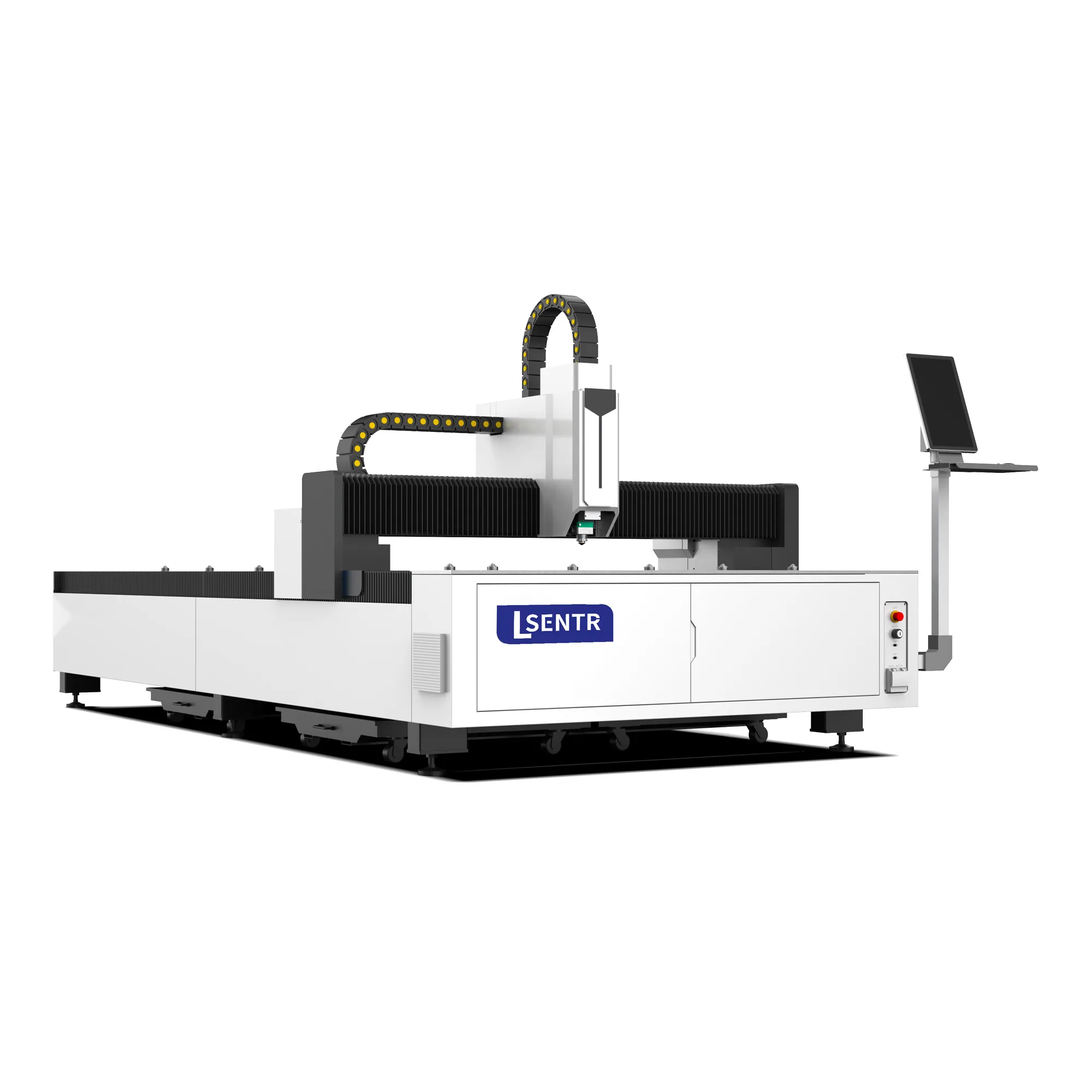
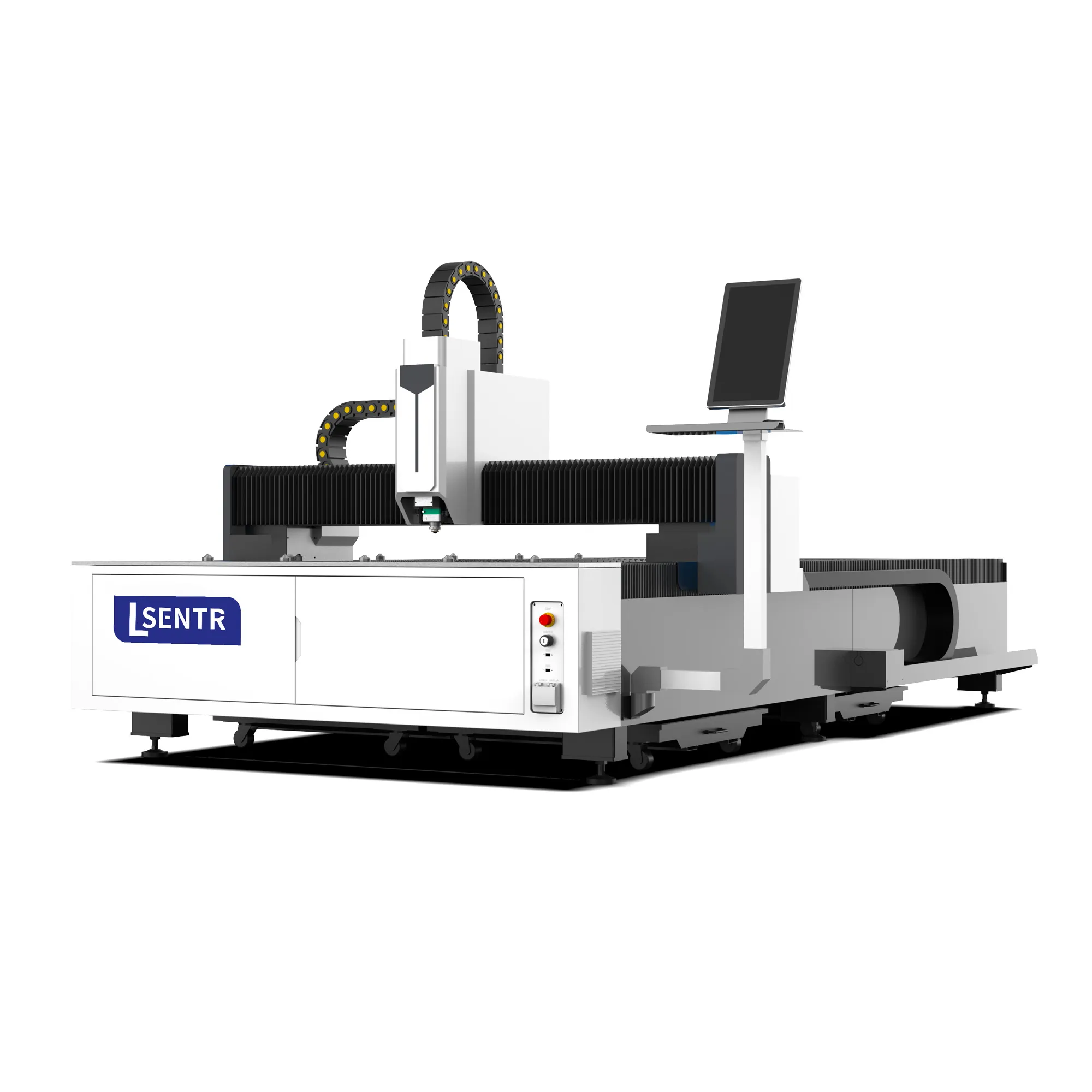
Machine appearance and supplied components follow the agreed configuration.
An open bed. A direct sheet-to-part workflow.
Share your sheet size, material and usual thickness. Compare the proposed machine, utilities and delivery scope in one quotation.
A single table laser cutter uses one work surface for loading, cutting and unloading. With the STR A, sheets sit on the slat bed while the CNC system guides the cutting head along the programmed shape.
Produce different contours and hole patterns from sheet stock for changing orders and part designs.
The open layout provides access for sheet loading, remnant handling and part collection.
Use a single cutting surface when separate exchange-table loading is not required by the production schedule.
Prepare the sheet on the slat bed before cutting begins.
The CNC system guides the head along the programmed shapes.
Remove the finished parts and remnants before loading the next sheet.
The same table handles the next sheet. Include changeover time when comparing daily output; maximum axis speed alone does not describe the complete production cycle.
A fiber laser cutting system concentrates laser energy into a small spot on the sheet. The material heats and melts along the programmed contour, while assist gas helps remove molten material from the kerf. The CNC system coordinates the cutting path and the head's movement.
The part drawing defines the shape. A cutting program adds a toolpath, entry points and process settings so the machine can produce the required profile from sheet stock.
For an internal opening, the process first makes a starting hole before following the contour. A part with many holes can spend considerable time piercing even when its total cut length is short.
Laser power alone does not define the result. Focus, nozzle condition, gas and the programmed motion must suit the material and the geometry.
Laser cutting is a thermal process. Closely spaced features, narrow strips and dense nests need a suitable cutting sequence and supporting strategy to manage heat and part stability.
Process background: TRUMPF's explanation of laser cutting. General process principles are not a cutting-capacity specification for the STR A.
Reference specifications for the STR3015A standard A machine. Laser power and cutting capacity are selected after reviewing the material and job.
| Machine type | Open-type single table fiber laser cutting machine |
|---|---|
| Working area | 3050 × 1530 mm |
| Laser power | Application-specific configuration; request the confirmed power options |
| Maximum moving speed | 100 m/min |
| Maximum acceleration | 1.0 G |
| X/Y positioning accuracy | ±0.03 mm |
| X/Y repeat positioning accuracy | ±0.02 mm |
| Transmission | Rack and pinion / dual drive |
| Published supply reference | 380 V, 50/60 Hz, three phase |
| Cutting materials | Carbon steel, stainless steel, aluminum and other compatible metals, subject to configuration |
| Maximum cutting thickness | Confirm by material, laser power, assist gas and representative sample test |
* Reference values from STR's existing STR3015A technical page, reviewed 20 October 2026. Confirm the final technical sheet and layout before ordering. Moving speed is not cutting speed; axis positioning figures do not establish finished-part tolerances.
Need to check a drawing or a particular thickness?
Request an application reviewThe source, cutting head, controller and motion system work as a package. The images below show components in STR's current A machine gallery; the quotation defines the exact brands and models supplied.
Supports the sheet and motion assembly. Check the construction, permitted sheet load and machine layout for the proposed build.

Carries the cutting head across the work area. Assess motion performance with your actual part geometry and cutting program.

Focus and height control are matched to the source and cutting task. Confirm the supplied head, optics and consumables.

Specify power around routine thickness, required edge quality and workload. Ask for the exact source model in the proposal.

Programs the sheet-cutting path. Confirm software, supported files, nesting functions and licenses with the selected configuration.

Transfers servo motion to the machine axes. Include inspection access and the delivered maintenance instructions in your review.
The STR A is intended for metal sheet cutting. Material grade, thickness, surface condition and the required finish determine the suitable process. It is not specified here as a machine for wood, acrylic or other non-metals.
| Material | Typical parts | What to confirm |
|---|---|---|
| Carbon / mild steel | Brackets, base plates, structural blanks | Grade, scale or rust, thickness and whether an oxidized edge is acceptable |
| Stainless steel | Enclosure panels, kitchen equipment blanks | Surface finish, visible-edge requirements and assist-gas specification |
| Aluminum | Panels, covers and lightweight components | Alloy, thickness, cut quality and source/head compatibility |
| Brass / copper | Decorative profiles and compatible metal parts | Reflective-material capability and a sample cut with the proposed configuration |
| Galvanized sheet | Cabinet and sheet fabrication blanks | Coating, extraction requirements and edge condition for downstream finishing |
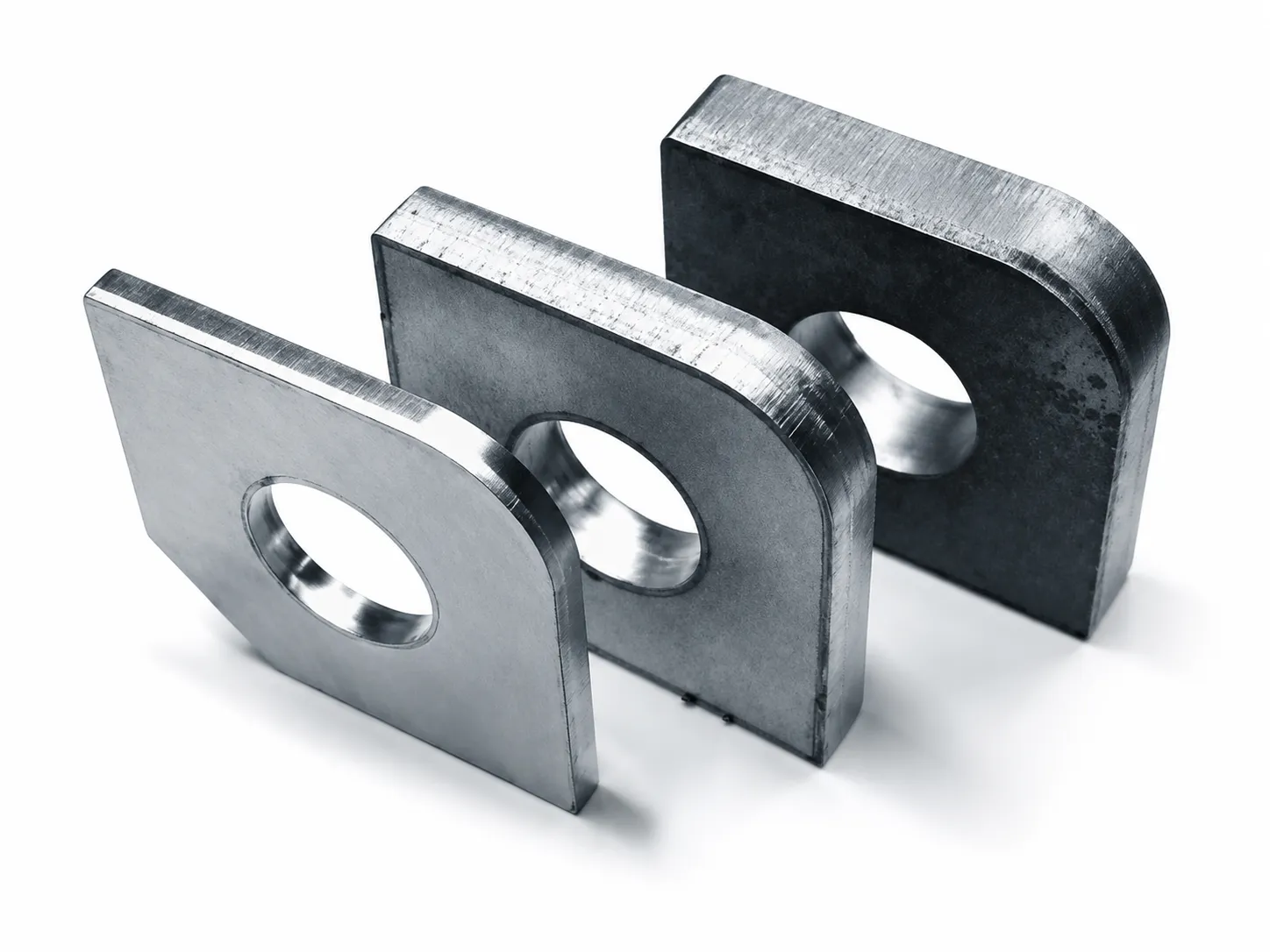
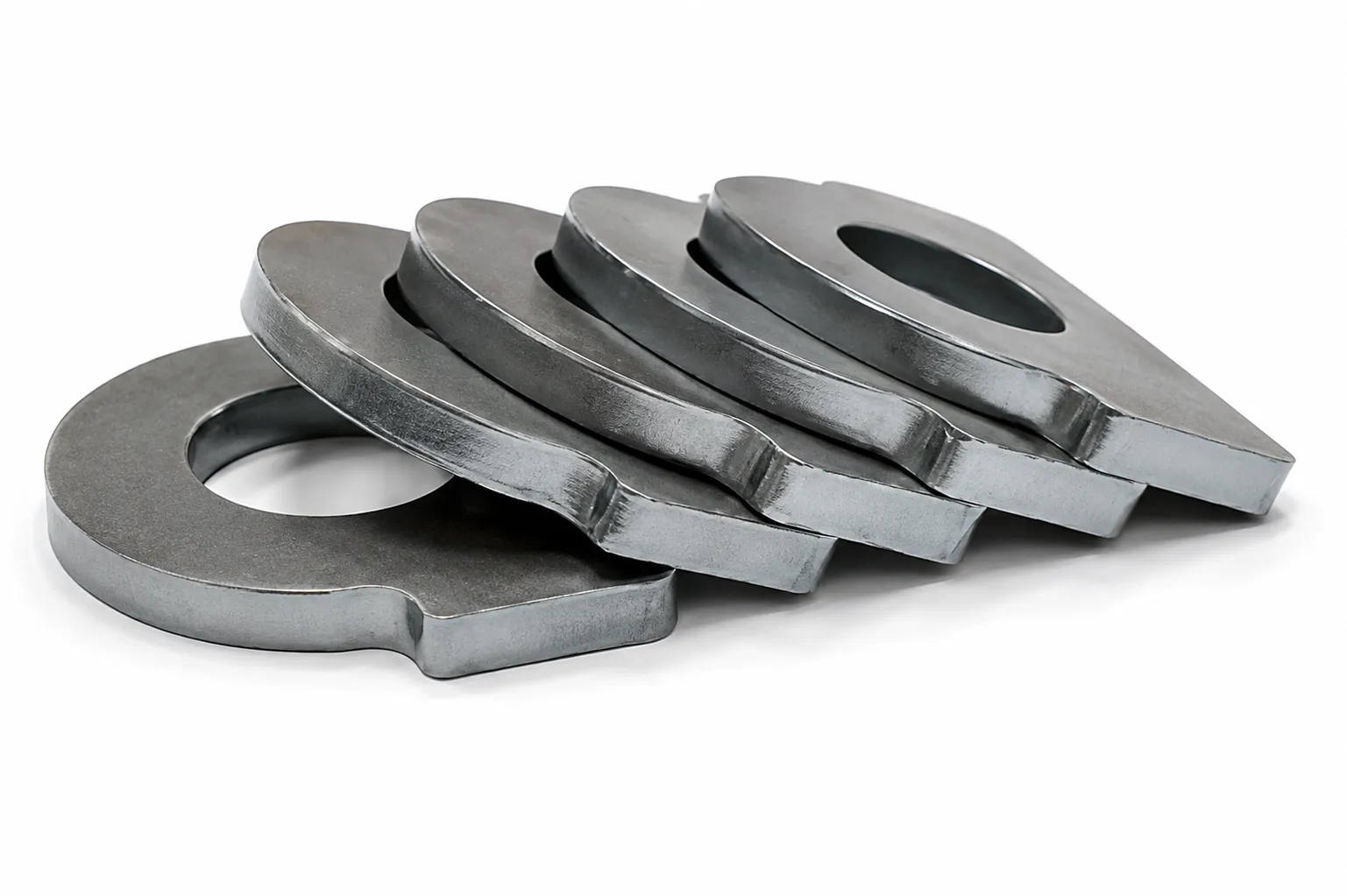
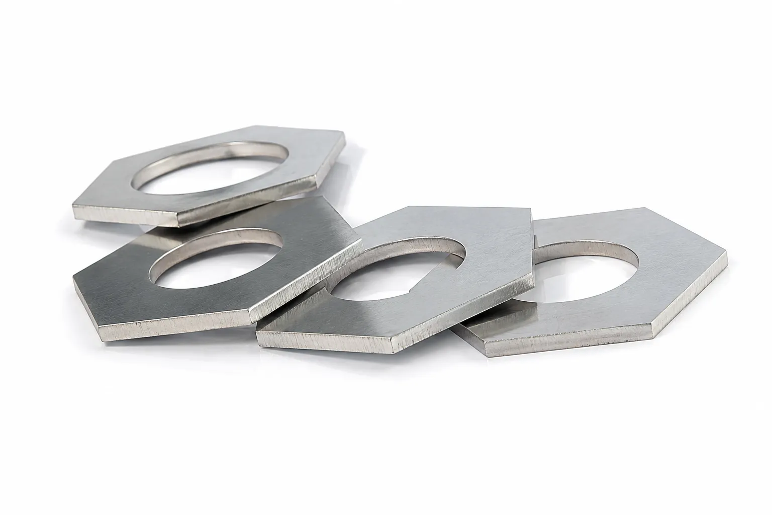
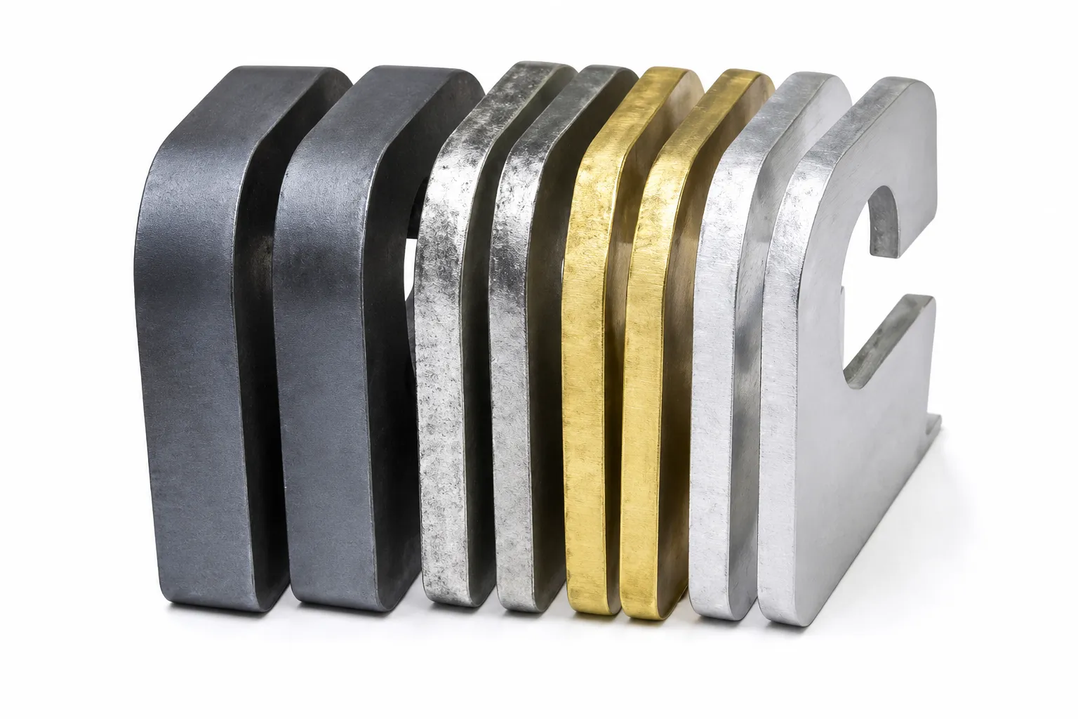
Gallery images show part shapes. Material grades, thicknesses, settings and cycle times are not provided with these images; use a job-specific sample test to assess your result.
Evaluate the machine around the parts that move through your workshop. Cutting is one stage of a fabrication process; the blank must also suit the bending, welding, fastening or finishing that follows.
Flat patterns can include outer profiles, mounting holes, ventilation slots and access openings. Check hole locations and bend allowances against the finished assembly, rather than reviewing the flat blank alone.
Changing part designs and mixed batches make drawing preparation and material handling important. Include both simple blanks and hole-intensive parts when comparing a sample job.
Visible surfaces, edge appearance and the next welding or finishing operation influence the cutting specification. State which face is cosmetic and which edges remain visible in the finished product.
Detailed lettering and patterns call for a review of small features, unsupported sections and part removal. Confirm that the chosen material and layout keep delicate shapes stable throughout the cutting cycle.
These are application examples for procurement discussion, not claims of named customer projects or industry approvals.
Assist gas affects edge condition, processing requirements and operating cost. Select it together with the material, thickness, proposed laser configuration and the operation that comes after cutting.
| Gas route | Main consideration | Review before selection |
|---|---|---|
| Oxygen | Supports a reactive cutting process and can leave an oxidized edge. | Check whether the edge needs treatment before the planned welding or coating operation. |
| Nitrogen | Used when reducing oxidation on the cut edge is important. | Review finish requirements together with gas supply, consumption and local cost. |
| Compressed air | May be an option where its resulting edge condition suits the job. | Include air preparation and the effect on downstream finishing; compare the complete process cost. |
General gas-selection background: Bystronic's assist-gas discussion. Gas routes are subject to the STR configuration and process review; this is not an operating-settings chart.
A clean-looking photograph is only part of the evaluation. Assess the edges, geometry and handling of a representative part against the requirements of the finished assembly.
Look at dross, edge roughness and oxidation. Decide what can go straight to the next process and what needs additional finishing.
Include the smallest important hole, narrow slot and tight corner in the trial. A large outer contour does not demonstrate these features.
Agree how the finished part is supported and measured. Axis positioning specifications and the tolerance of a cut component are different measures.
Review more than a single selected piece. Include parts from a representative layout and record the condition of the sheet, consumables and process.
Job record: material grade and surface, sheet thickness, drawing revision, proposed source/head, assist gas, required edge finish and critical dimensions.
Result record: accepted and rejected features, finishing required, representative part photos, measurement method and the scope of the reported cycle time.
Compare a complete sheet cycle with the same boundaries. A quoted cutting-only time and a cycle that includes loading, piercing, sorting and unloading do not measure the same work.
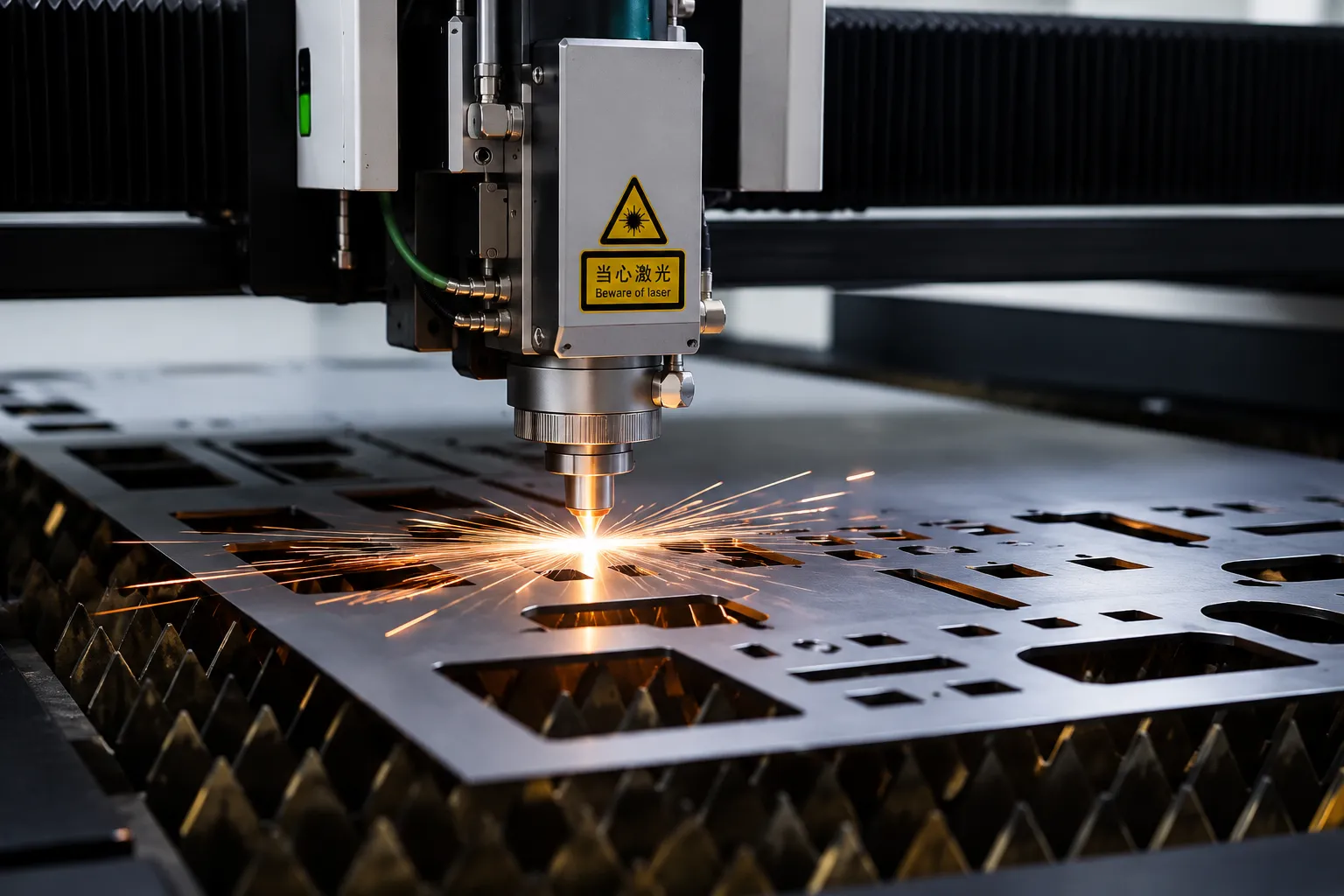
List your routine material and thickness first, then the occasional maximum. A machine that can separate one thick sample may not deliver the edge quality or cycle time required for regular production.
Include the smallest holes, detailed contours, finish requirements and daily quantity. Compare a representative drawing at the proposed power, gas and process settings.
| Decision | STR A single table | Exchange-table system |
|---|---|---|
| Sheet changeover | Loading and unloading share the cutting table; cutting pauses for changeover. | A separate table can be prepared while the other is cutting, subject to the machine's operating design. |
| Best reason to evaluate | Varied work where the single-table handling cycle fits the daily output target. | Repeated sheet production where changeover is a meaningful bottleneck. |
| Workshop planning | Allow access, unloading space, extraction and the required protective measures around the open table. | Check the complete machine and exchange-table footprint, access and guarding. |
Need a different loading workflow? Compare enclosed and exchange-table laser cutting
Send a representative production part rather than only its overall dimensions. A clear drawing helps the discussion cover feature quality, material use and the handling cycle.
If available, include a 2D CAD file such as DXF together with a dimensioned PDF. Confirm the accepted input formats and any conversion requirements for the controller in the proposed machine; this page does not promise that every CAD format is supported directly.
Have a mixed batch or a difficult part?
Include it in your application inquiryRequest pricing for a defined configuration. A bare machine price and a delivered, ready-to-install package may cover different equipment and services.
Ask for an itemized proposal with the machine configuration and the equipment needed at your site.
Plan access to consumables and the delivered maintenance instructions before the machine arrives. Replacement demand depends on the job, operating environment and component condition; a fixed annual quantity is not a reliable promise for every workshop.
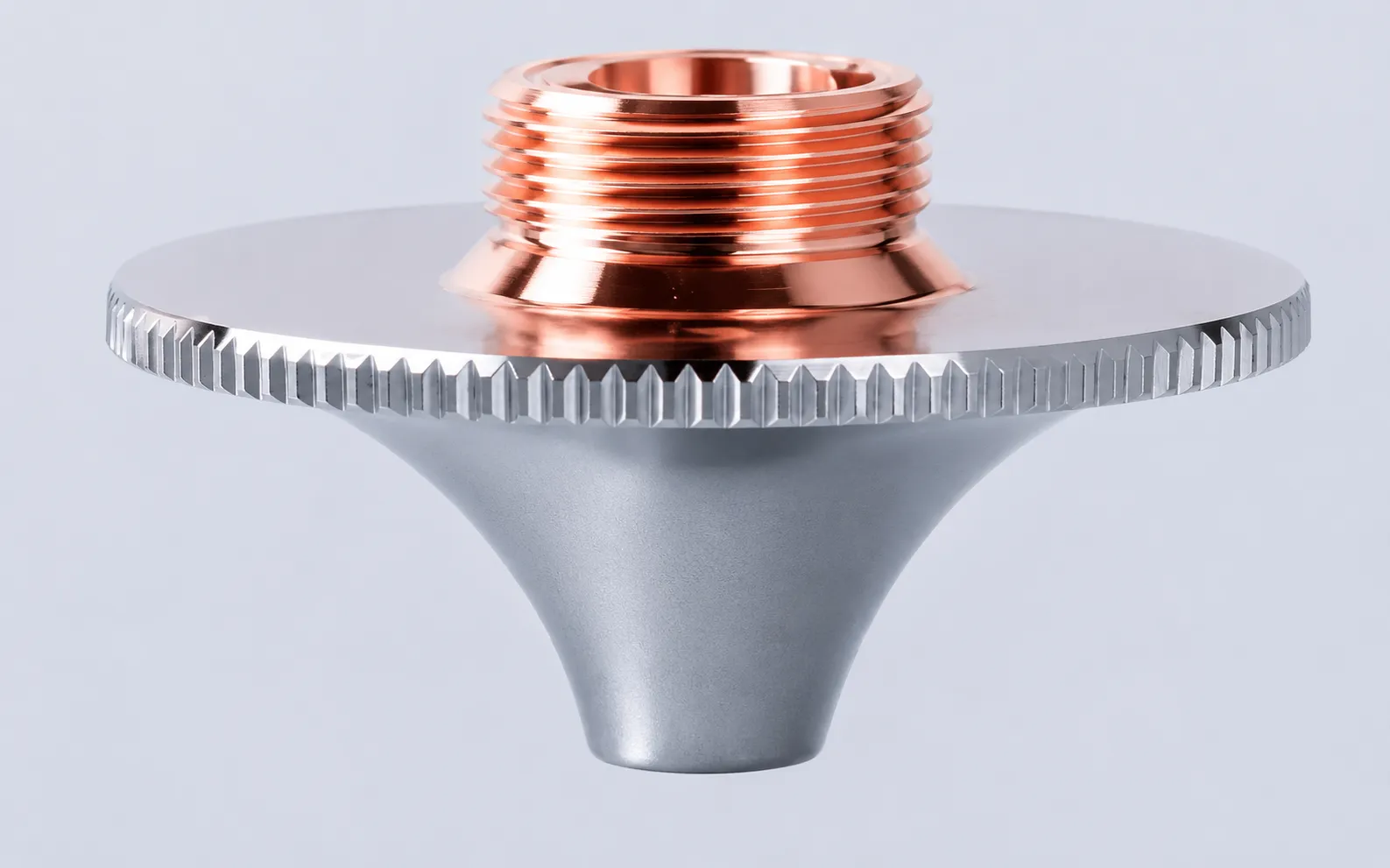
Keep the specified nozzle types available. Inspect for damage or contamination and follow the cutting-head instructions for replacement and alignment.

Identify the exact window specification and inspection procedure. Optical handling and any cleaning must follow the component manufacturer's instructions.

Include the correct replacement part for the supplied head. Damage can affect the assembly and height-sensing system.
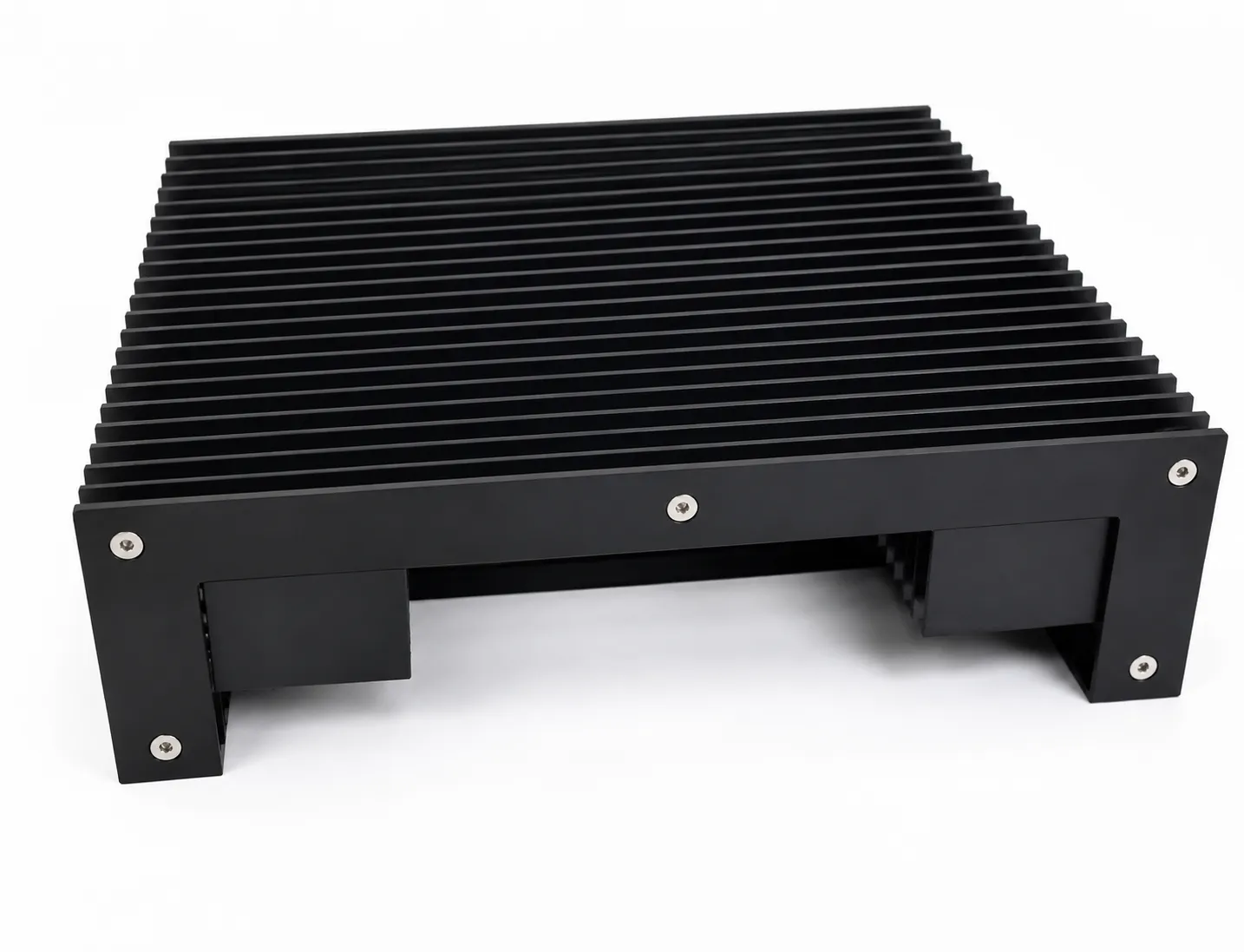
Inspect covers for damage and keep access to the motion system clear. Use the delivered maintenance procedure for the axes and drive components.
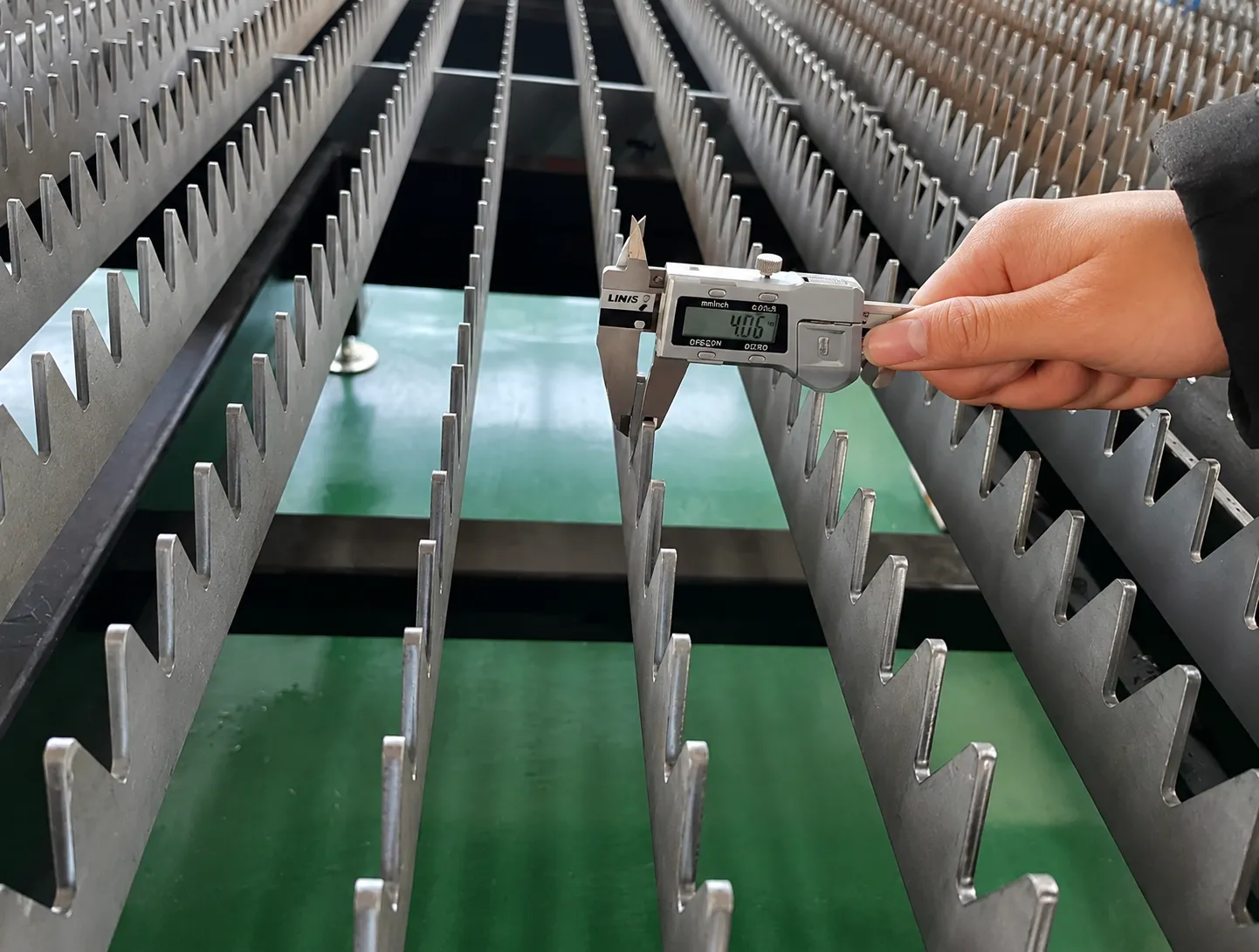
Monitor slag buildup and the condition of sheet supports. Plan cleaning and replacement around the material, layout and maintenance instructions.
The chiller, extraction system, gas preparation and motion components also need the inspection and service specified for the supplied equipment. Establish a maintenance log and identify the parts that must be stocked locally.
When requesting spares, send the machine identification, component model, part code and a clear photo. Do not order a nozzle, lens or ceramic ring on appearance alone.
Keep the equipment specification, test job and delivery responsibilities in the same project record. That makes the quotation easier to compare and gives both parties a clear basis for acceptance.
| Stage | Record to agree |
|---|---|
| Application review | Material, drawing revision, routine thickness, part quantity, edge criteria and site conditions. |
| Configuration proposal | Working area, source/head/controller, supplied accessories, software, utilities and exclusions. |
| Sample evaluation | Representative part or nest, process conditions, measurements, finish and cycle-time boundaries. |
| Delivery & startup | Packing, transport terms, unloading responsibility, installation, training, documentation and support contacts. |
The project proposal determines the agreed scope and terms. This planning outline is not a promise of a particular delivery time, certification or service package.
Confirm site voltage, phase, frequency and total installation load. Size the gas supply, cooling and extraction for the actual configuration.
Check the machine layout, delivery access, unloading method, sheet loading and space for finished parts and remnants.
Arrange a site-specific laser safety assessment, suitable engineering controls, extraction and trained operation. Follow the delivered instructions and applicable local requirements.
Agree on the sample job, supplied documentation, installation/training scope, warranty exclusions and contact route before shipment.
It is a CNC metal cutting machine with one worktable used for loading, cutting and unloading. The STR A uses an open table for flat-sheet processing. It has a different handling cycle from a machine with two exchange tables.
Evaluate it when your sheet size, material and daily quantity fit a single-table workflow. Include loading and unloading time when estimating output. Share a representative drawing so the configuration can be reviewed against the part you need.
Power is selected around material grade, routine and maximum thickness, assist gas, required edge condition and production quantity. Request the confirmed power options and a sample result for your typical job.
There is no single thickness value for every STR A configuration and metal. Confirm the material, source, cutting head, gas and required result together. Ask for routine production performance as well as maximum separation capability.
This page specifies the standard A machine for flat-sheet cutting. Tube cutting and bevel cutting require a separately specified machine or configuration. Include those requirements in the inquiry so they can be routed to the appropriate product.
Confirm those terms in the project proposal for your destination and supplied configuration. Ask which services are included, how support is delivered, and which components and consumables are covered or excluded.
Send your country, material grade, usual and maximum thickness, sheet size, daily workload, available electrical supply and a representative part drawing. Add any edge-finish requirement, required delivery date or workshop constraint.
Only if the proposed configuration, material and required edge result suit that process. Compare air preparation, resulting oxidation, any finishing required and the total job cost. The assist-gas section explains the selection factors.
No. Maximum axis travel speed is different from cutting speed and total sheet-cycle time. Geometry, piercing, cut quality, loading and part collection all affect the output you can achieve.
Start with the parts specified for the supplied cutting head and machine: nozzles, protective windows, ceramic components and any other identified wear parts. Agree on the part codes and maintenance instructions; quantities depend on your actual jobs and usage.
Compare a different cutting layout or explore the next process after sheet cutting. Each link takes you to the relevant STR equipment page.
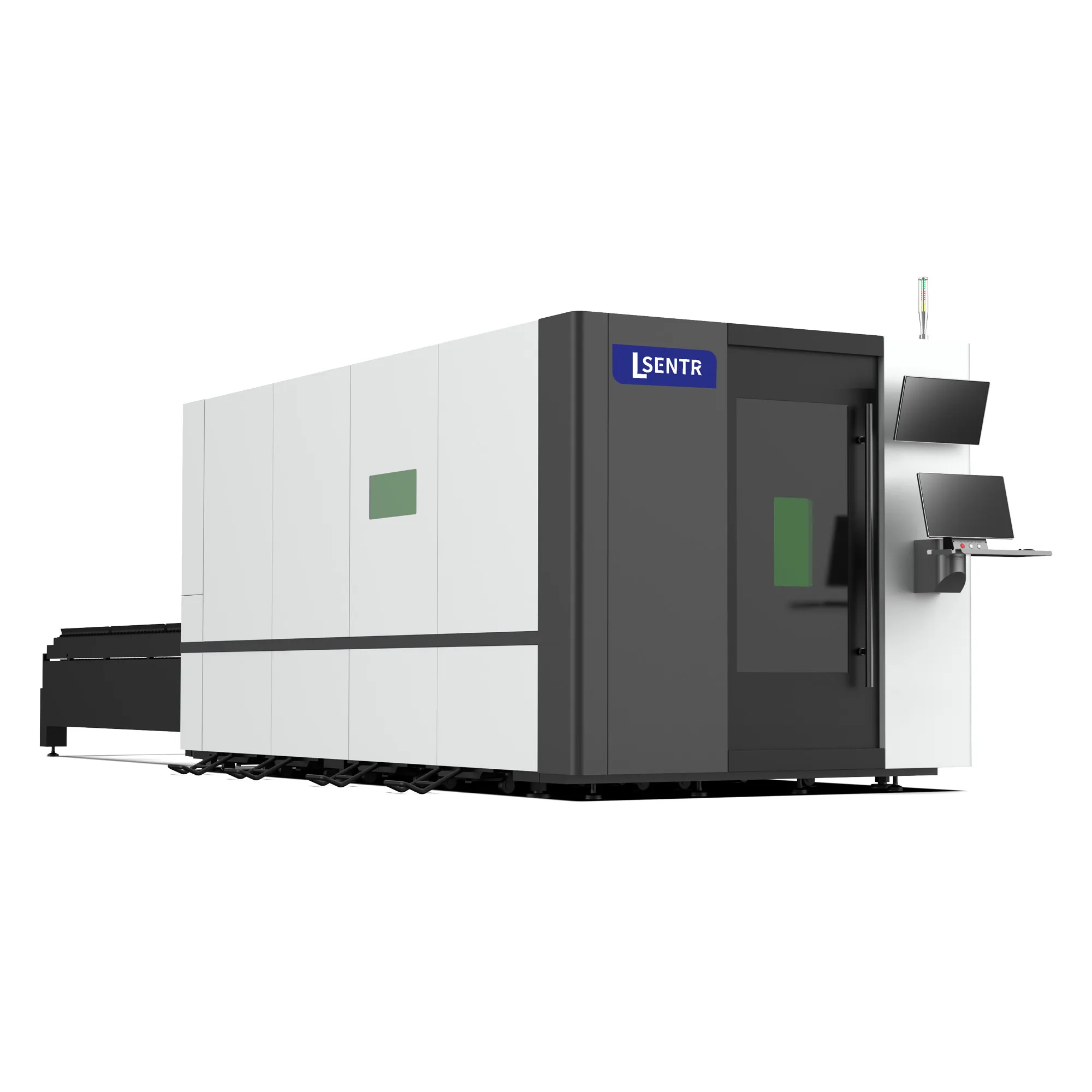
Compare when preparing the next sheet and managing changeover are important to the production plan.
View exchange-table lasers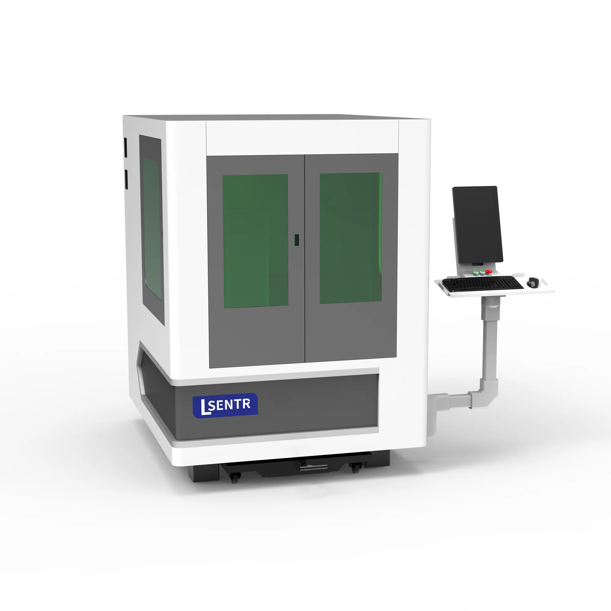
Evaluate a compact enclosed cutting layout around the size of your parts and the available workshop space.
View D series lasers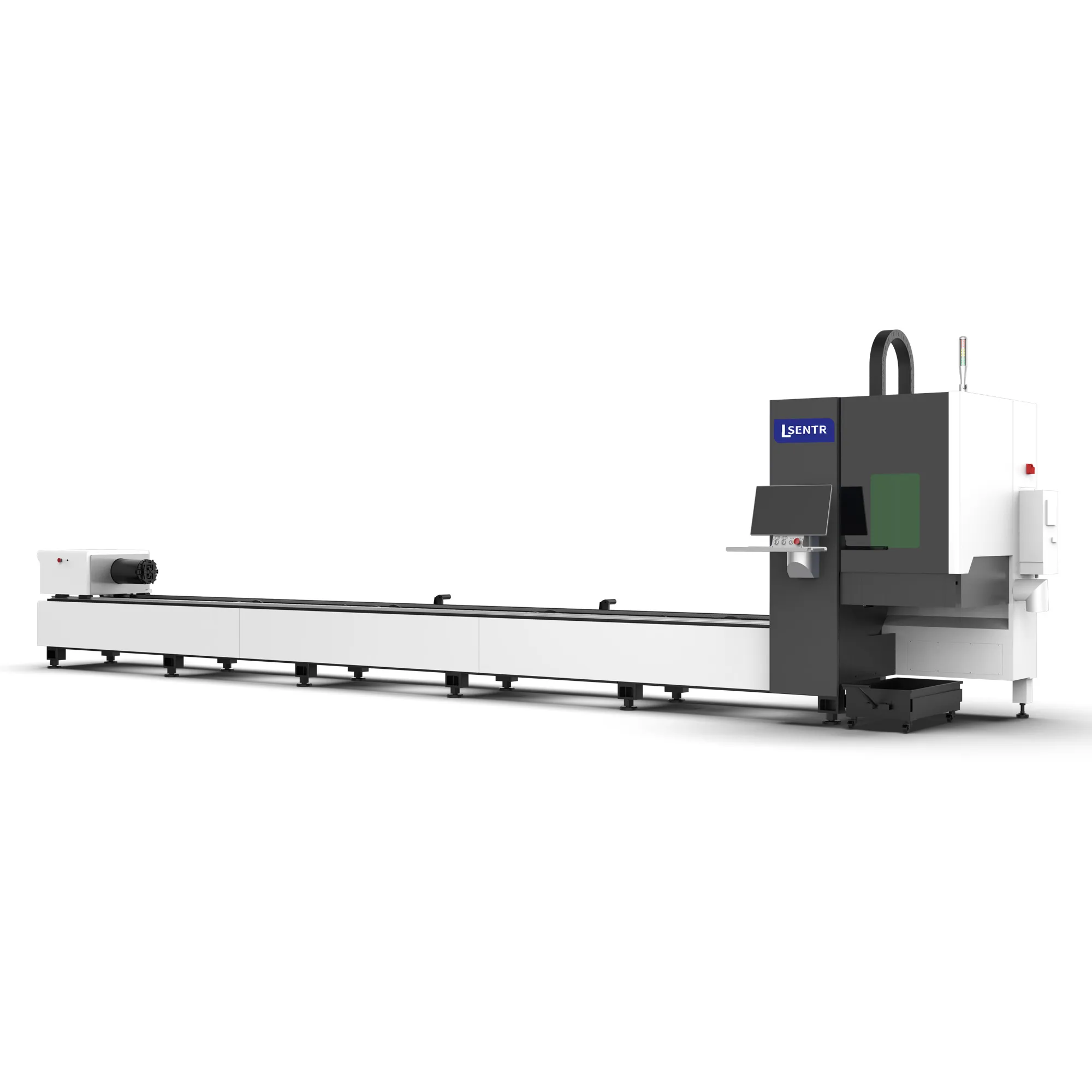
Use a dedicated tube-cutting route when your work includes tube or profile components rather than flat sheet alone.
View tube laser cutters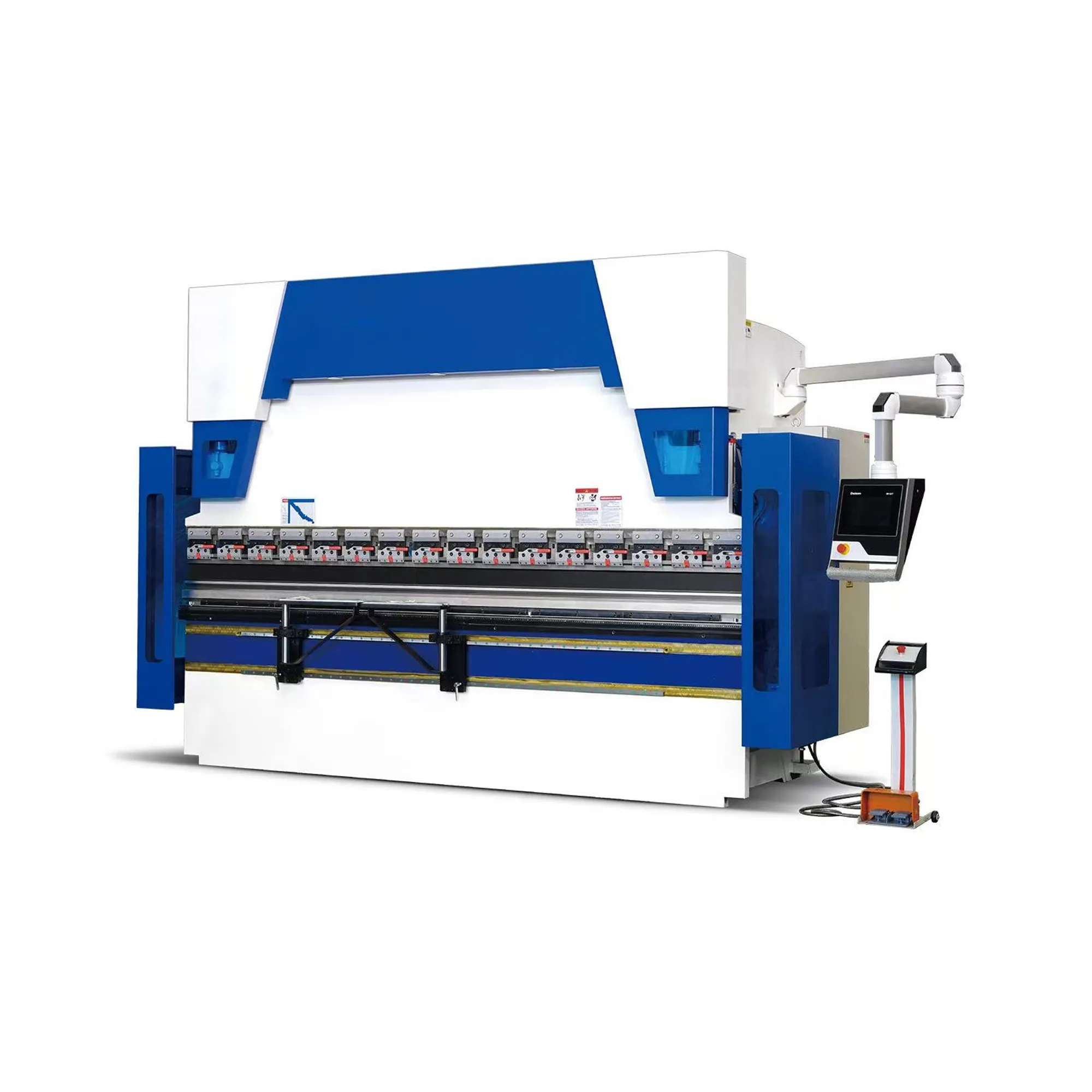
Plan the bending operation for cut blanks. Match the forming equipment to the material, part length and required bends.
View press brakes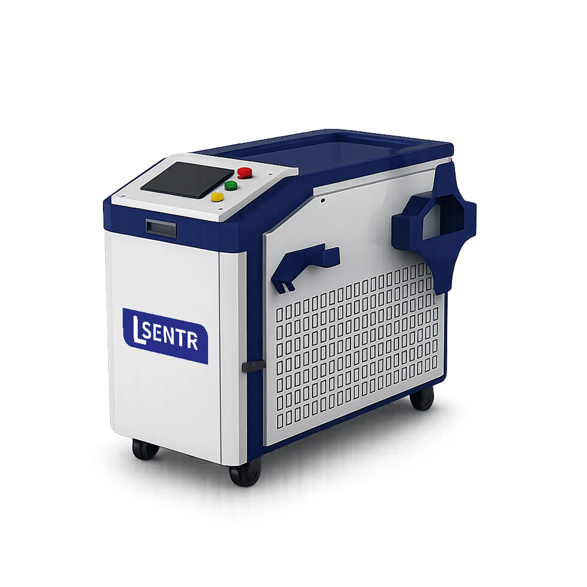
Explore joining equipment for the cut or formed parts in your assembly, with a separate review of material and joint requirements.
View laser weldersInclude your finished-part drawing and production sequence. Review how cutting, bending and joining fit together before selecting the equipment.
Discuss a fabrication workflowStart with the metal parts you need to make. Add your sheet size, thickness and workload so the discussion starts with your production requirements.
Prepare and review your requirements summary, then send it through the STR contact page or email.
Discuss your application with STR. We supply industrial laser cutting, welding, cleaning and press brake equipment for metal fabrication.
Tell STR what you need to cut. We will review the application and discuss a suitable configuration.