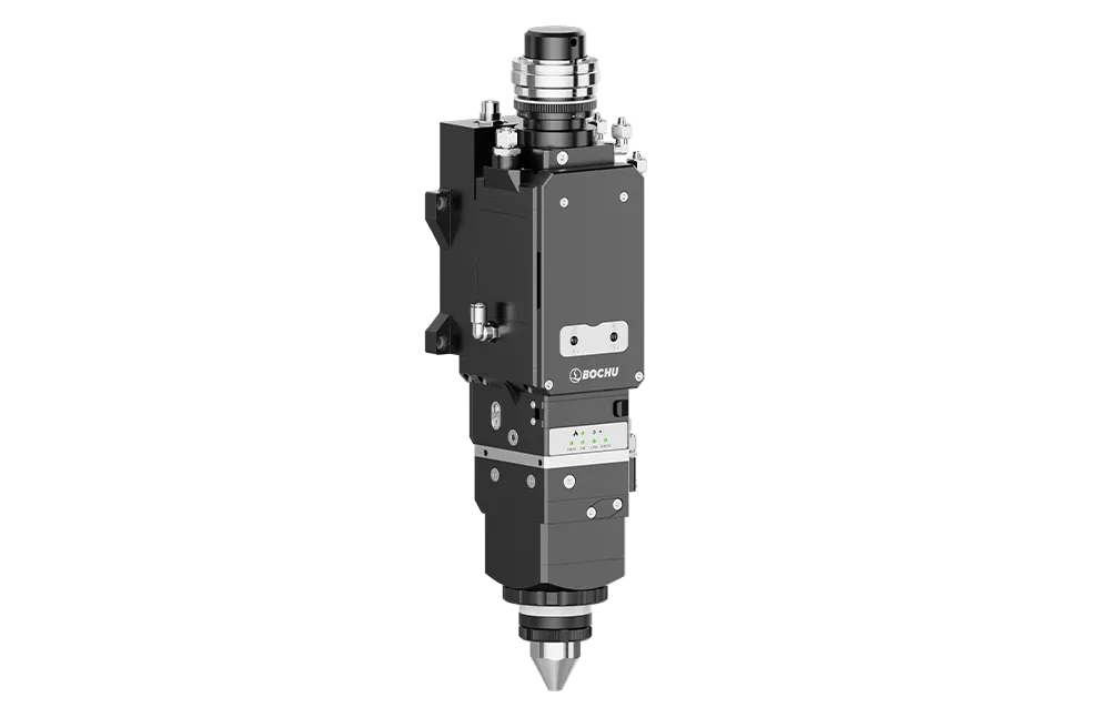
Bevel cutting head
Confirm the offered head and its optical, power and gas compatibility. Review the required tilt, clearances, nozzle arrangements, protective optics and service access.

STR AP · Configure the cut around your joint drawing and edge requirements.
A bevel fiber laser cutting machine uses a tilting cutting arrangement to produce specified inclined edges on metal plate. The STR AP review starts with the required joint section, material and finished dimensions, then matches the head, control, laser and handling package to that job.
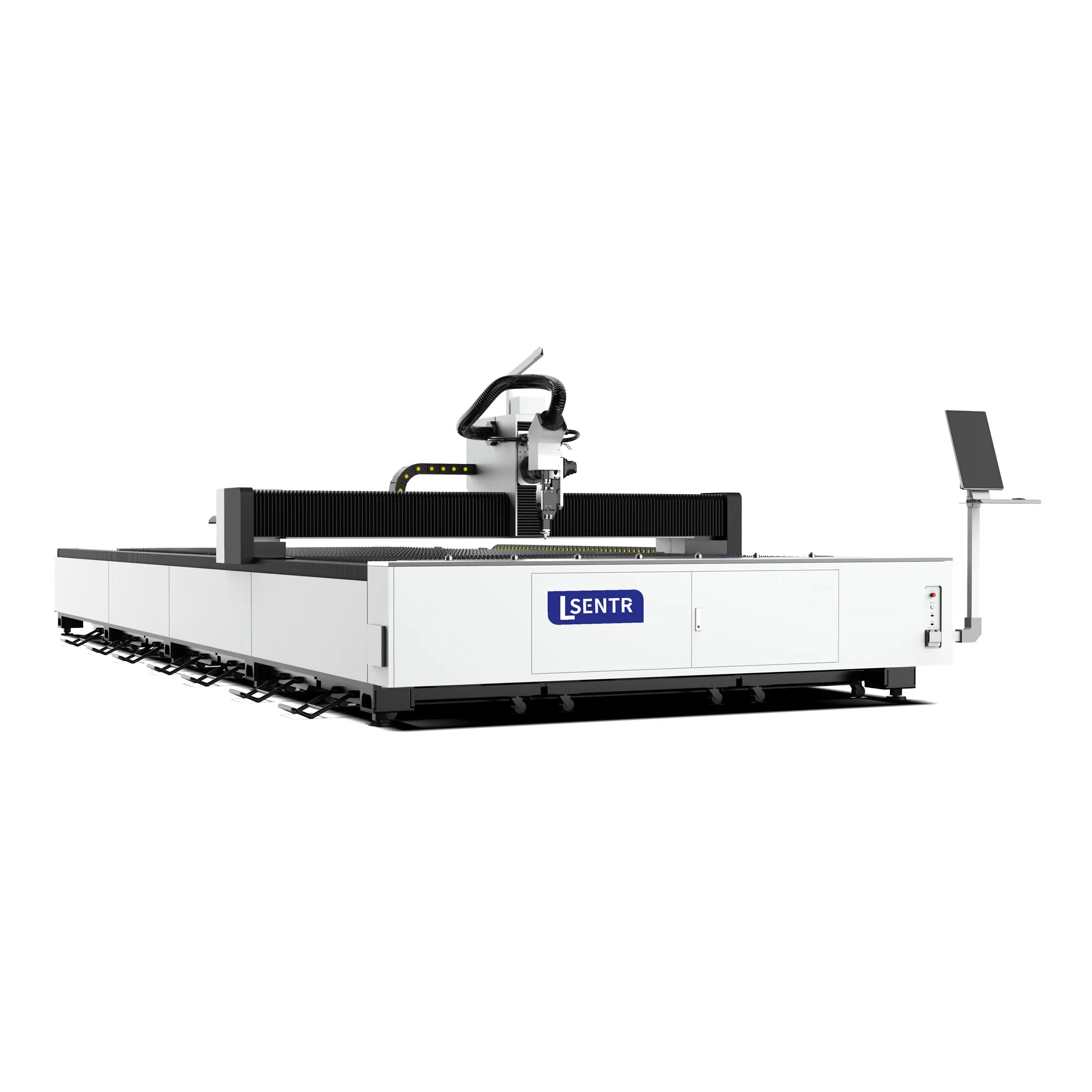
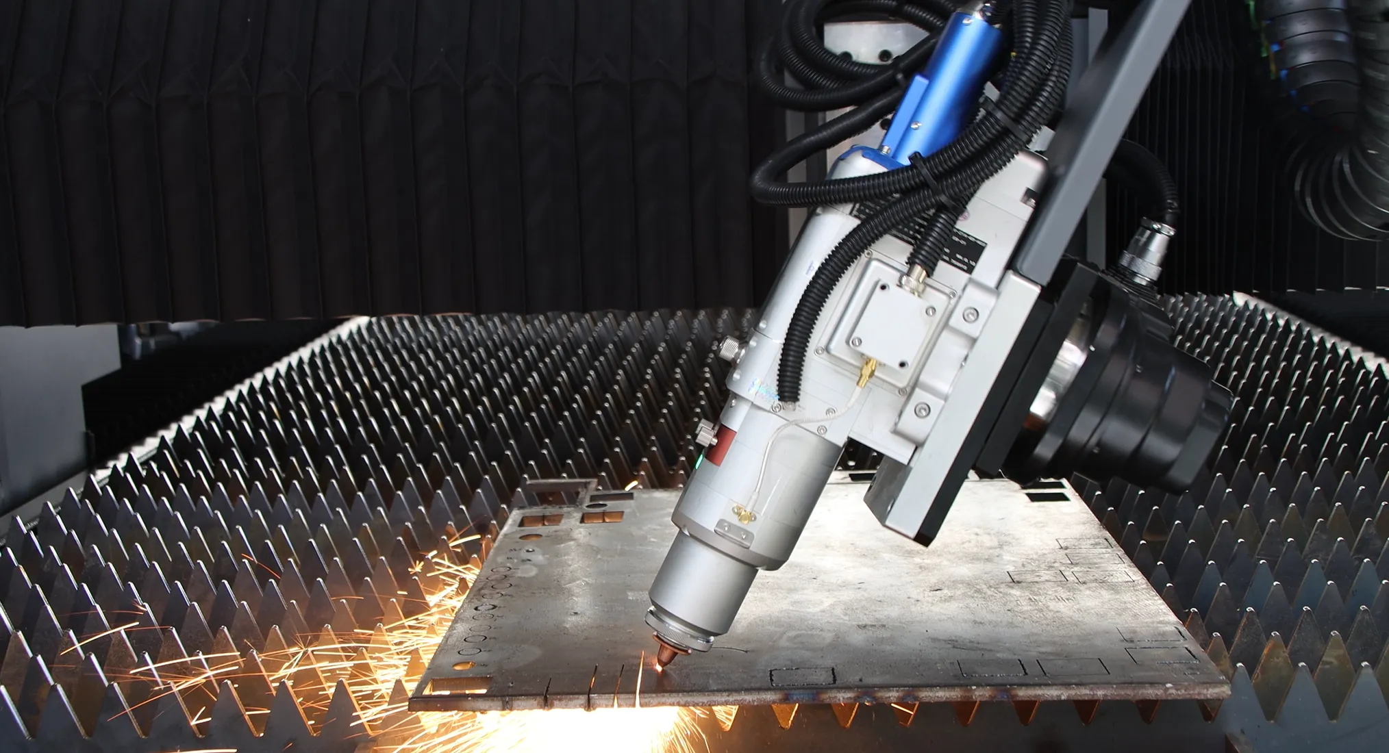

AP machine, cutting process and component references from the existing STR page. Confirm the final supplied assembly in the technical offer.
Sheet-metal cutting and bevel-edge preparation, reviewed against the actual part.
Send a dimensioned part drawing, bevel detail and material specification. Mark the datum face, angle convention, root face and surfaces that will be joined.
Bevel cutting becomes relevant when the edge section is part of the component's function: a specified weld preparation, an inclined fit or an edge that would otherwise require a separate operation. The question is whether the proposed laser process can produce the required section consistently while keeping the part usable for the next operation.
Bring the drawing revision and section views. A label such as “45° bevel” alone leaves the angle reference, land, direction and finished dimensions unresolved.
Compare the existing route of cutting, handling, edge preparation and inspection with a proposed AP route. Count every operation that remains after laser cutting.
Mark which edges need a bevel and which remain square. Review supported operations, sequence and clearance with the offered programming package.
Specify angle, root face, orientation and dimensional datums.
Review material, thickness, head motion and cutting conditions.
Measure the bevel and both relevant faces, not only the top contour.
Record cleanup, assembly and the buyer's joining requirements.
Use the published AP model information to begin the discussion. The dated technical offer should define the actual machine, software functions, utilities and acceptance conditions for your application.
| Item | Reference or required confirmation |
|---|---|
| Model reference | STR3015AP |
| Published working area | 3000 × 1500 mm; confirm usable sheet and part envelope with head tilt and clearances. |
| Published angle reference | 0° to ±45°; define the angular datum and verify the requested material, thickness and contour. |
| Bevel geometry | Supply section drawings for single- or double-sided preparations, root face and finished dimensions. |
| Laser and process | Confirm source, power, head, assist-gas route and application trial for the required edge. |
| Motion and control | Identify rotary/tilt arrangement, compensation, programming functions, file formats and included licenses. |
| Quality acceptance | Agree dimensional, angular, root-face and edge-condition criteria with an inspection method. |
| Installation and supply | Confirm full layout, auxiliaries, electrical/gas requirements, extraction, guarding, documents and training. |
* Area and angular range are references published on STR's existing STR3015AP page, reviewed 22 October 2026. They are not a verified cutting-capacity chart. A head's angular envelope does not establish that every plate thickness, contour or joint section can be cut at its limit. Final configuration and trial conditions require confirmation.
The angle of one bevel face is different from the included angle between two assembled faces. State the drawing's angular reference explicitly. Also define the root face, sometimes called the land: the remaining square portion at the edge, where the specified joint design includes one.
An inclined face shifts the edge position through the thickness. Identify which face controls the external profile, hole size or assembly fit; a top-view outline is not a complete bevel definition.
Mark the material side, upper/lower face and bevel direction. Include the datum used for angle inspection so the quotation, program and sample report describe the same geometry.
Give the root-face dimension and its tolerance, if required. Define where bevels begin, end or change, including corner details and connections to square-cut edges.
V, Y, X and K are useful joint-description terms, but they do not replace a dimensioned section. Single/double sides, access and pass strategy need a review of the actual part.
Consider a hypothetical 12 mm plate with a 2 mm root face. The bevel height is therefore 10 mm. For a planar face at angle α from the plate normal, horizontal offset b = (t − c) × tan α and inclined face length l = (t − c) / cos α.
| Defined input or result | α = 30° | α = 45° |
|---|---|---|
| Plate / root face | 12 / 2 mm | 12 / 2 mm |
| Bevel height | 10 mm | 10 mm |
| Horizontal offset b | 5.77 mm | 10.00 mm |
| Inclined face length l | 11.55 mm | 14.14 mm |
These are invented geometry inputs. The calculation omits kerf, taper, compensation, thermal effects and actual process conditions. Face length is not a guaranteed laser cutting thickness or proof that AP can produce this joint. It also does not specify the included angle of an assembled joint.
The practical lesson is to submit thickness and angle together. A square-cut thickness claim cannot establish an inclined-edge result. Validate the proposed material/angle combination and its dimensional datums in the same trial.
Bevel cutting combines the intended edge section with tool orientation, focus/height control, assist gas, path planning and part support. The program must account for where the physical head can move as well as where the laser intersects the plate.
Review corners, lead-ins, lead-outs and the cutting order on the actual nest. The chosen strategy should preserve the required faces while keeping the work stable during cutting and recovery.
External process background: Messer's bevel laser cutting explanation discusses adapting lead-ins, run-outs and cutting sequence to the bevel. It explains the general process; it does not establish STR's controller functions or supplied software.
Check head/body clearance near sheet edges, clamps, slats and adjacent parts. Nominal table size alone does not define usable travel at every tilt and orientation.
Internal profiles, small radii and bevel transitions can require different strategies from a straight outside edge. Include the smallest critical feature in the trial drawing.
Review the order of internal and external cuts, remaining support and how parts will be removed. A loose or tilted part can interfere with subsequent operations.
Agree how an operator checks the work and resumes after a stop. Confirm supported recovery functions and their training scope in the proposed control package.
The AP images below identify component references used on the existing page. Select the actual head, motion/control package and laser source against the application; the commercial offer should list the supplied manufacturers, models and licenses.
Confirm the offered head and its optical, power and gas compatibility. Review the required tilt, clearances, nozzle arrangements, protective optics and service access.
Identify the actual axis arrangement, travel limits and calibration procedure. Review how orientation and positional compensation are maintained in the supplied system.
Check file import, section definition, bevel assignment, simulation, compensation and operator editing. List included functions and any separately licensed tools.
The laser source, chiller, gas system, extraction and machine structure also belong in the configuration. A controller screenshot or branded head photograph is not confirmation of the delivered bill of materials.
| Material / requirement | What to provide and verify |
|---|---|
| Carbon steel plate | Grade, scale/surface condition, thickness and joint detail. Define acceptable oxide, dross and remaining cleanup for the downstream operation. |
| Stainless steel | Alloy, cosmetic face and required edge condition. Review assist gas, surface handling and the joining/finishing requirements. |
| Aluminum alloys | Exact alloy and condition, part geometry and edge requirements. Confirm the proposed laser/head package and representative trial. |
| Other alloys or coatings | Submit material information for explicit application and extraction review. Do not infer suitability from a steel sample. |
| Increasing thickness or angle | Review the combined condition, feature size and required face quality; do not extrapolate a square-cut capacity. |
A process that cuts through the plate may still fail the joint requirement. Inspect the angle, root face, surface condition and fit, and define whether finishing is permitted before the next operation.
Start with the approved joint details for plates that will be assembled. Check the required fit and datums, including any edge that remains square for locating or clamping.
Identify the short contours, inside corners and support conditions that can make the part more demanding than a long straight bevel sample.
Use recurring parts to compare cutting plus preparation with the current route. Record setup, reorientation, inspection and handling for a fair batch comparison.
When the edge serves a fit rather than a weld, define the contact surface and functional dimensions. Do not replace fit requirements with a generic weld-preparation description.
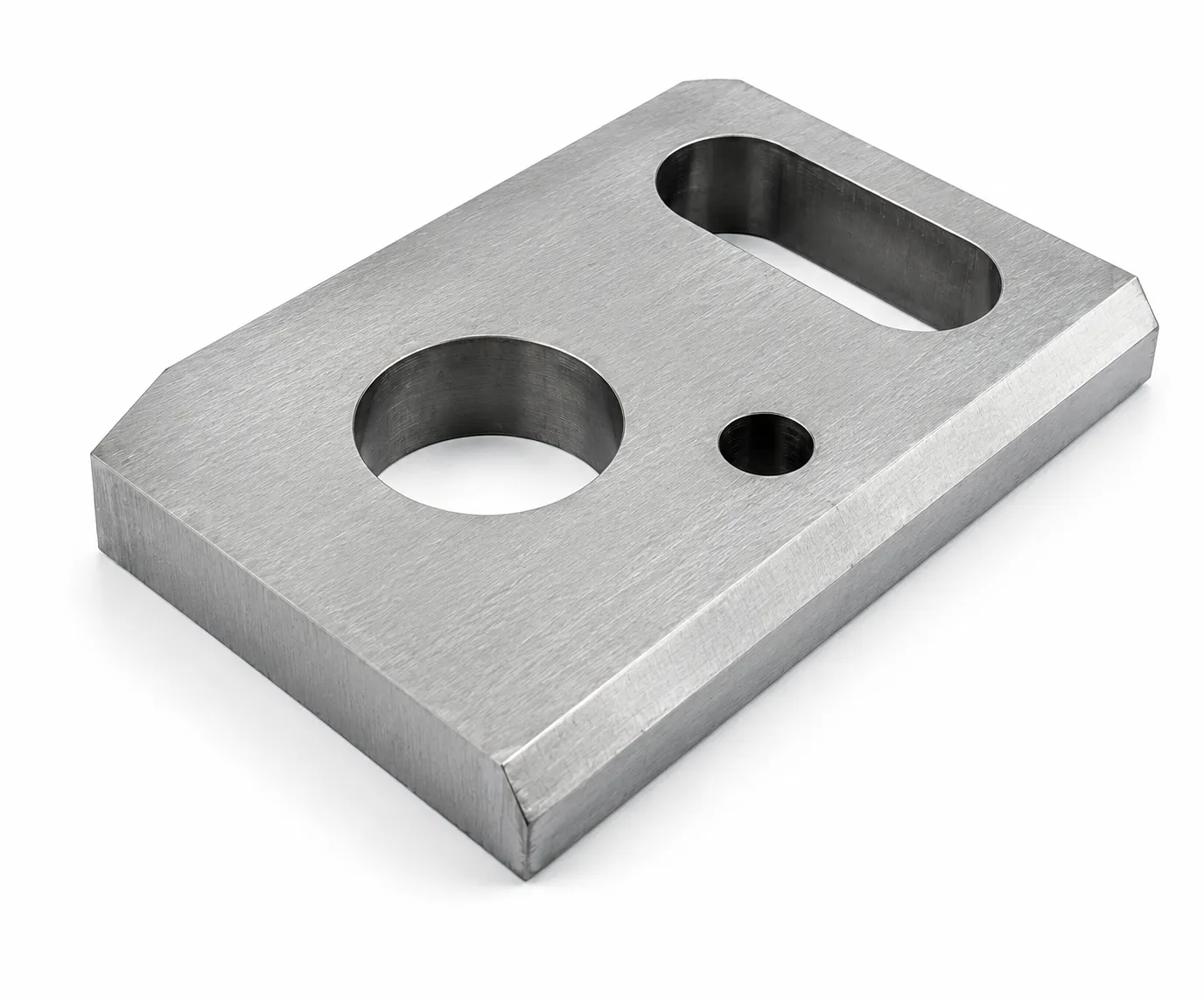
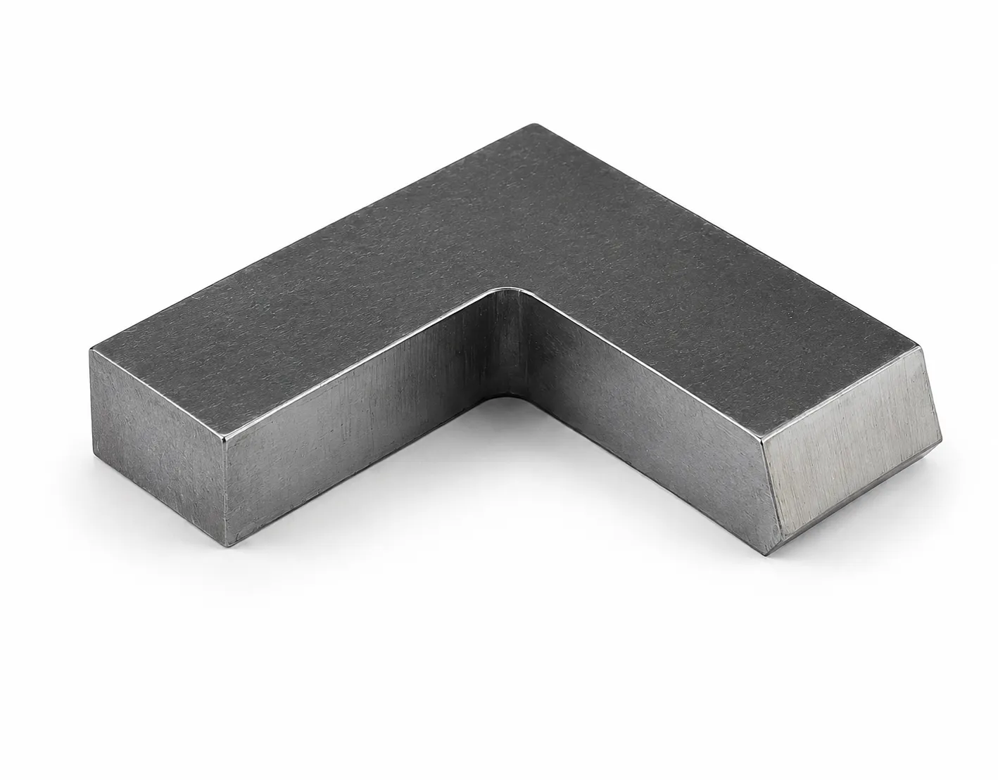
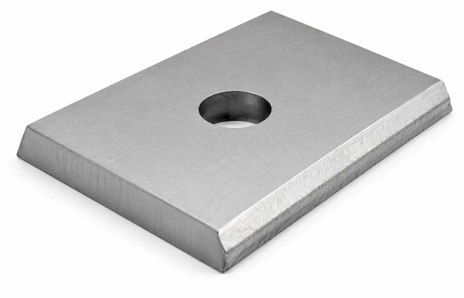
These images come from the existing AP page. They show sample geometry and presentation; no material grade, measured angle, thickness, cut time or acceptance result has been verified from the photographs.
Record drawing revision, material grade and measured thickness, stock condition, machine/laser/head build, software version, assist gas and the agreed process. Identify each sample and where measurements were taken.
Include straight edges, corners, transitions and the smallest relevant feature. Inspect repeat samples and relevant locations across the work area where the agreed acceptance plan requires them.
| Feature | Acceptance discussion |
|---|---|
| Bevel angle | State datum, nominal value, tolerance, measurement tool and locations; distinguish one face from an included joint angle. |
| Root face / land | Specify dimension, variation allowed and how it is measured along the relevant edge. |
| Finished contour | Identify controlled top/bottom dimensions, internal features and position relative to the drawing datums. |
| Bevel surface | Define acceptable striations, dross, oxide, local defects and any permitted cleanup with a repeatable inspection method. |
| Corners and transitions | Inspect start/end regions and transitions between square and inclined edges, not only the middle of a straight cut. |
| Assembly and joining | Check agreed fit-up and the buyer's preparation requirements. Qualify the downstream welding process separately where required. |
| Repeatability and cycle | Agree sample quantity, run conditions, inspection records and whether handling, cleanup and rework are included in the reported time. |
Laser bevel cutting prepares an edge; it does not by itself qualify a weld, prove joint strength or remove every cleaning requirement. Use the buyer's approved joint detail and welding requirements to define the preparation scope.
Compare the same part, section and acceptance result. Review the current sequence and the proposed AP sequence, including any operations that remain outside the machine. Avoid judging cost from cutting time alone.
| Task | Record for both routes |
|---|---|
| Programming and setup | Drawing preparation, section definition, fixtures, calibration and first-piece approval. |
| Cutting and preparation | Actual process time, pierces, passes and any separate edge-preparation operation. |
| Handling | Moves between stations, part reorientation, access, sorting and recovery. |
| Finishing and inspection | Dross/oxide removal, permitted touch-up, measurements, fit checks and rework. |
| Operating resources | Gas, power, consumables, labor and maintenance under the compared conditions. |
Already have a representative part and current preparation route?
Prepare an AP application reviewIf your normal work only needs square-cut sheet profiles, start with the A single-platform configuration. If access and sheet turnover dominate the job, also compare the B exchange-table layout. These pages address different selection tasks; their specifications do not establish AP performance.
Follow the supplied inspection and calibration procedure, particularly after a collision, component change or maintenance event. Confirm the operator checks and escalation process with the service team.
Use the parts specified for the offered head. Keep protective optics and nozzle condition within the supplier's procedure; consumption depends on process and operating conditions.
Confirm purity, pressure/flow requirements, cooling conditions and extraction maintenance for the final configuration. Arrange service access without obstructing loading and head travel.
Define backups for programs, parameters and calibration records. Confirm included updates, support channels, spare-parts identification and the response arrangements in the contract.
Maintenance intervals, consumable life, warranty terms and service response need the actual equipment manual and commercial agreement; they are not inferred from gallery images.
Before ordering, align the technical sheet, sample report and commercial offer. Identify what is included in the machine package and what the workshop must provide.
Send the receiving workshop's location and available utilities with the drawing. This allows the proposal to address the installation context as well as the cutting task.
A square-cut edge is nominally perpendicular to the plate faces. Bevel cutting intentionally produces an inclined edge section. The section requires angle, orientation and dimensions through the thickness, in addition to a top-view contour.
No. An angular envelope does not establish cutting capacity for every thickness, material or contour. Confirm the angle convention, usable envelope and the requested combination in an application trial.
Submit dimensioned sections rather than relying on a joint name. STR needs to review side access, root face, contours, machine/head configuration, software and pass strategy before confirming the requested preparation.
That depends on the required edge condition, actual cut result and the buyer's welding preparation requirements. Agree permitted cleanup and test the complete route. A photograph cannot prove a universally ready-to-weld edge.
Provide material grade, usual/maximum thickness, bevel section, smallest features, required edge condition and output. Select the laser, head, gas and motion/control package together; power alone does not define the result.
Identify both edge types in the drawing. Confirm supported operations, tilt positions, transitions and programming functions in the proposed package, then include relevant combinations in the sample trial.
Agree angular datums, top/bottom dimensions, root-face dimensions, measurement tools and sample locations. Machine-axis accuracy is not a substitute for a finished-part acceptance report.
Send a dimensioned drawing and joint sections, material grade and thickness, blank size, output, required inspection and workshop location/utilities. Include the current preparation route if you want to compare complete production cost.
Choose the edge-preparation process and the handling arrangement around the actual work.
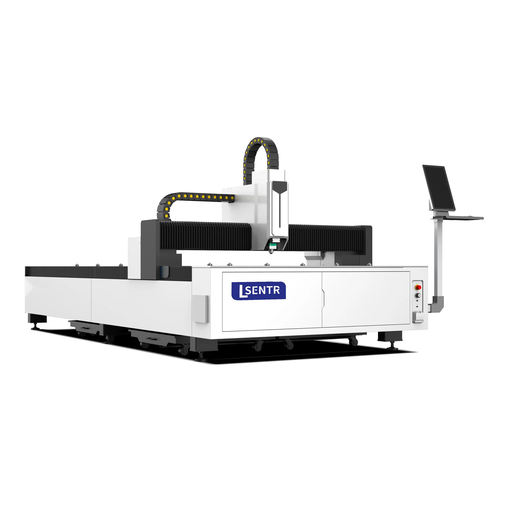
Review the standard sheet-cutting configuration for jobs that need square profiles.
View standard A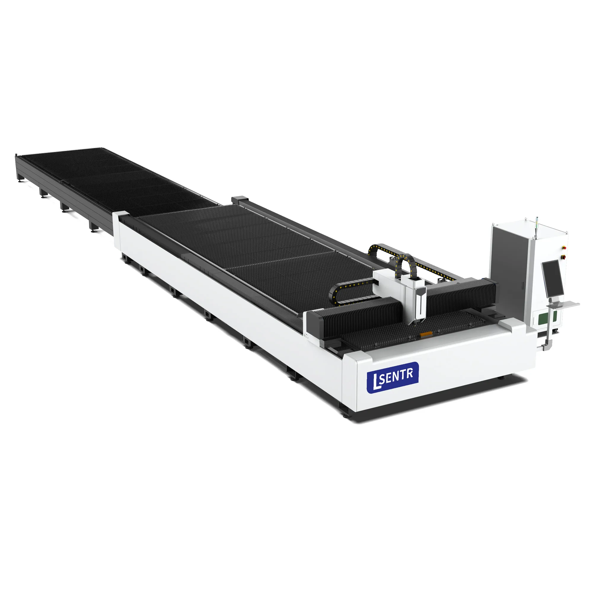
Review sheet preparation, exchange travel and the complete handling route.
View the B layout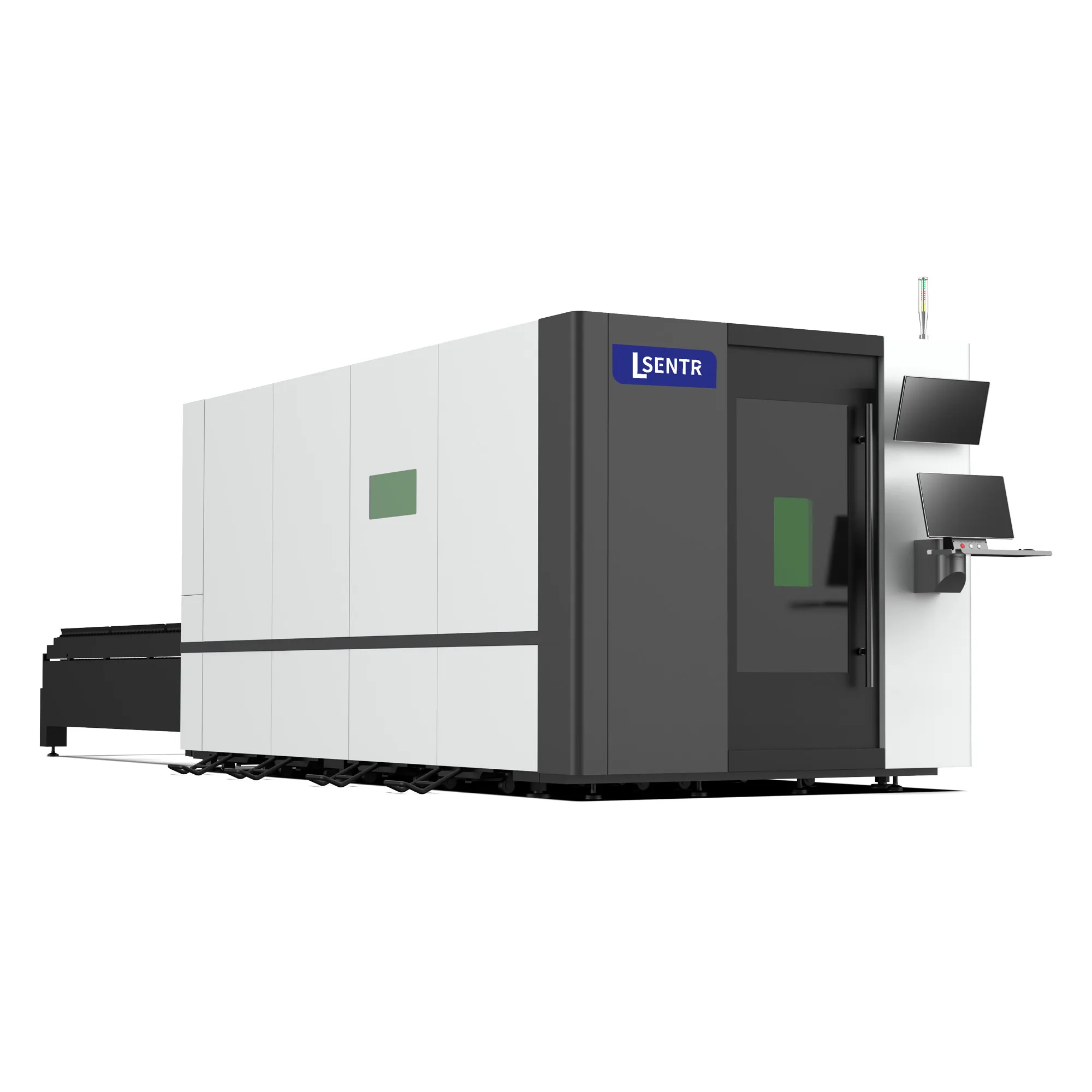
Compare an enclosed cutting position with external sheet preparation and access requirements.
View the BD layoutSend a dimensioned part drawing and joint sections. Specify the angle reference, root face, material, thickness and required edge inspection. Include the current preparation route and workshop utilities.
Prepare and review your requirements summary, then send it through the STR contact page or email. This form does not submit an inquiry.
Discuss your application with STR. We supply industrial laser cutting, welding, cleaning and press brake equipment for metal fabrication.
Tell STR what you need to cut. We will review the application and discuss a suitable configuration.