Bed and sheet support
The slat bed supports sheets and cut parts. Sheet flatness, slat condition and the position of small parts matter to how the nest behaves. Establish the allowed loading and the supplied support arrangement for both tables.

STR B · Sheet access with a planned table-change cycle
The STR B is an open exchange-table fiber laser cutting machine for sheet metal work. Its layout combines an accessible cutting area with a separate table-handling position. Evaluate the machine, material flow and required site protection together before choosing the configuration.
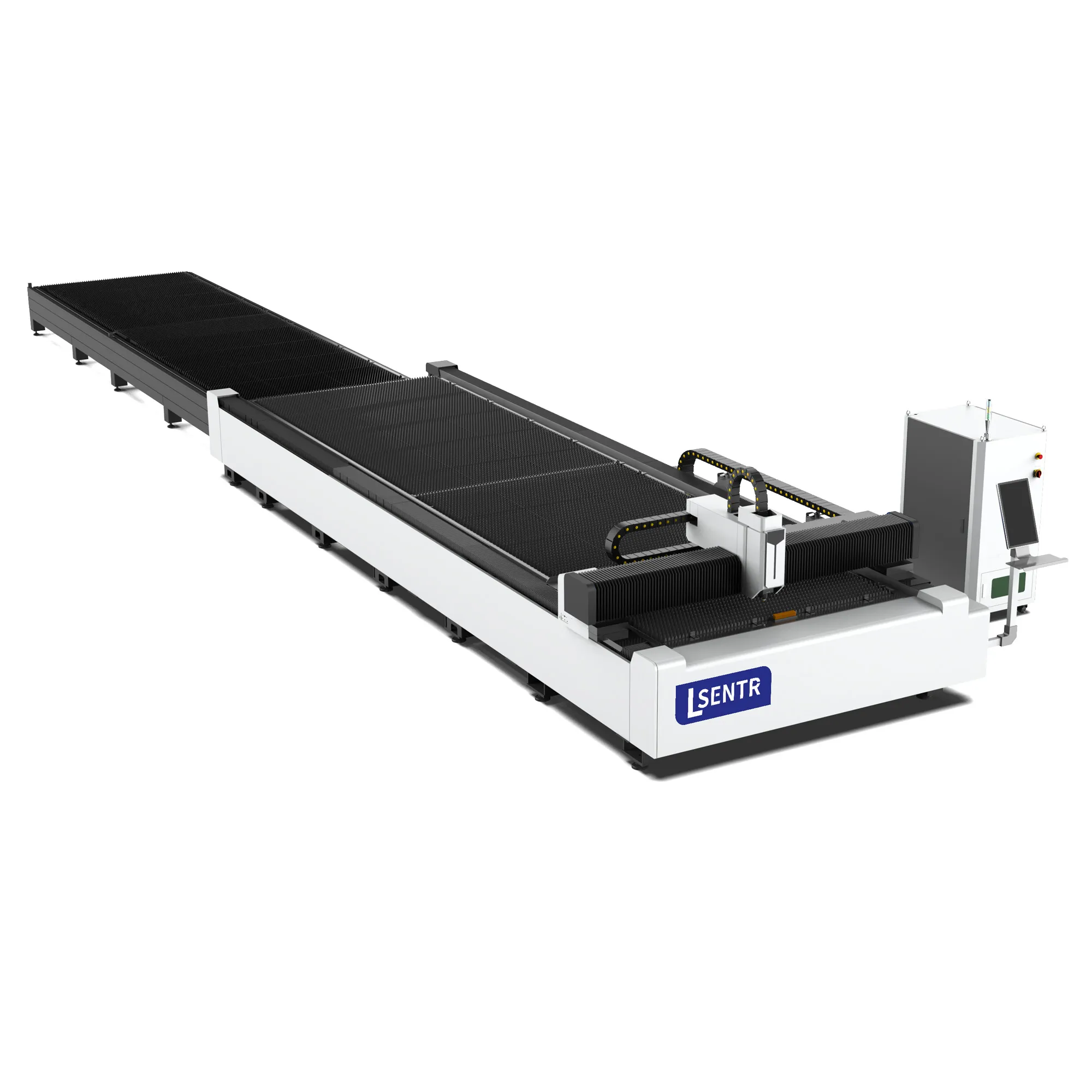
Original STR B catalog view. Appearance, dimensions and supplied equipment follow the agreed specification.
Plan access, cutting and the next sheet together.
Tell STR how you load the sheet, collect parts and clear the remaining skeleton. Add material, thickness, sheet weight and production demand so the proposal addresses the whole job.
An open exchange-table layout separates the cutting position from the table prepared for the next cycle. The layout can support permitted preparation alongside cutting, but the actual operating sequence and the site's protective arrangements determine which tasks can overlap.
Study where the lifting device approaches, where the operator stands and where parts are placed. An open view of the bed does not mean that every side is an approved loading point.
Part collection, skeleton removal, slat inspection and next-sheet positioning all compete for this space. A second table is useful only when its preparation keeps pace with the cutting task.
Open construction changes the site-planning task. Define the operating zone, access arrangements, extraction and protective configuration with the equipment supplier and the site's qualified personnel.
The CNC follows the approved nest at the cutting position.
When permitted, collect parts, remove the skeleton and position the next sheet.
Use the machine's approved access checks and exchange procedure.
Record handling and exchange work as part of the production cycle.
An exchange table and an automatic sheet loader are different functions. The quotation must identify the equipment actually included.
The configuration must connect the material and drawing to the machine, worktable and supporting equipment. The items below define a useful proposal; numeric values need a B-specific technical specification.
| Product identity | STR B open exchange-table sheet laser cutter; exact model to be identified in the proposal |
|---|---|
| Usable cutting area | Effective travel, accepted sheet dimensions and edge-clearance conditions |
| Table arrangement | Exchange sequence, table levels/positions, loading area and permitted handling method |
| Table load | Allowed sheet mass and load distribution for each supplied table |
| Laser source and power | Source model and rated power for the proposed material and production task |
| Cutting head and control | Head model, CNC, software functions, licenses and included accessories |
| Motion and accuracy | Axis specifications and test conditions, distinguished from finished-part tolerance |
| Utilities and auxiliaries | Electrical supply, gas preparation, cooling and extraction requirements |
| Installed layout | Machine and exchange envelope, protective arrangements, handling routes and service clearances |
| Handover scope | Documentation, installation, training, acceptance and applicable support terms |
Machine dimensions cannot be inferred from the catalog image. Working area, power, speed, acceleration, accuracy, load and exchange-time values require confirmation for the offered model.
The B catalog view shows the open machine and an extended table arrangement. Use the actual general arrangement drawing to locate loading positions, the table-change envelope and supporting equipment before committing floor space.
The slat bed supports sheets and cut parts. Sheet flatness, slat condition and the position of small parts matter to how the nest behaves. Establish the allowed loading and the supplied support arrangement for both tables.
The beam, guides and drives position the head relative to the sheet. Evaluate the offered mechanical build, motion specifications and maintenance access with their test conditions; a catalog silhouette does not establish beam material or a performance rating.
The source provides optical power; the head delivers the focused beam and assist gas. Confirm source/head compatibility, supported functions and the material process as a package rather than selecting by a brand logo alone.
The CNC runs the cutting and permitted machine sequence; nesting determines how parts are arranged on the sheet. Check file import, licenses, included functions and operator training against your existing drawing workflow.
Confirm the actual exchange arrangement, permitted load and operating sequence. Loading access, standing positions and movement clearances must reflect the supplied mechanism rather than a generic two-table diagram.
Locate extraction equipment, duct access and the chiller alongside the machine. Confirm what is included in the proposal and what the site provides, including the utility and maintenance requirements of those auxiliaries.
The practical attraction of an open layout is access to the work area. Its usefulness depends on a defined material route: where a sheet arrives, how it is lifted and positioned, how parts leave and where the skeleton is stored. Map these activities around the actual exchange envelope.
| Workshop task | Question that affects the layout | Record to request |
|---|---|---|
| Sheet delivery | Can the lifting device approach the permitted loading position with the intended sheet? | Loading method, sheet mass and access drawing |
| Part collection | Will operators sort at the table or move the cut sheet to a separate sorting area? | Unloading sequence and part/skeleton destinations |
| Table exchange | Which areas must remain clear and which activities may overlap? | Exchange envelope and approved operating procedure |
| Site access | How are the operating zone and surrounding routes controlled? | Installed protective configuration and site responsibilities |
| Service access | Can the supplied components and auxiliaries be reached by the specified procedure? | Service clearances and maintenance instructions |
Open construction is not a laser safety classification, a compliance certificate or permission to approach during cutting. The protective configuration and approved procedures must cover the actual installed system.
When allowed outside handling finishes before cutting ends, the next sheet can be ready for exchange. If clearing and loading take longer, a faster cutting program can leave the system waiting for the outside table. This is a handling bottleneck, not a reason to infer a faster exchange specification.
Hypothetical steady-state model, one sheet per cycle, with all permitted handling fully overlapping cutting. Excludes start/end effects, stops, changeovers and rejects. It is not a B test result; actual overlap may be smaller.
| Job | Cutting | Handling | Exchange | Other | Sequential | Overlapped |
|---|---|---|---|---|---|---|
| Longer contour cycle | 10 | 6 | 1 | 2 | 10 + 6 + 2 = 18 | max(10, 6) + 1 + 2 = 13 |
| Sorting-led cycle | 3 | 9 | 1 | 2 | 3 + 9 + 2 = 14 | max(3, 9) + 1 + 2 = 12 |
In the sorting-led example, cutting faster does not remove the nine-minute outside task. Compare part separation, skeleton removal and next-sheet supply before choosing an upgrade. Measure your own workflow with a stated timing boundary.
General industry context: material-handling bottlenecks in laser cutting. The numbers above are independent illustrative assumptions, not source-system or STR performance figures.
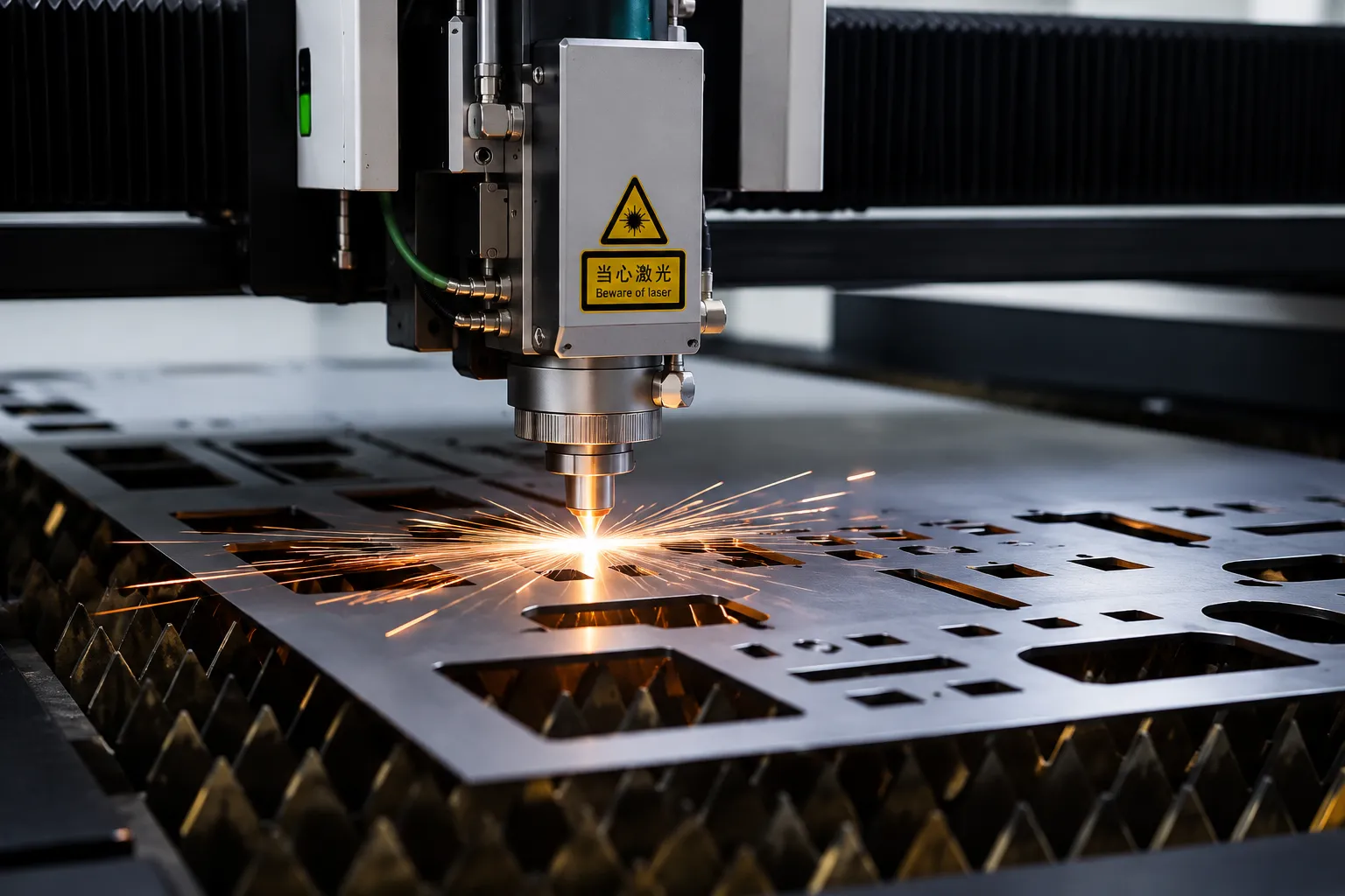
A cutting program converts drawing geometry into pierces and contours. The focused beam heats a local region while assist gas helps clear material from the kerf. Many small holes impose a different task from a long outside profile.
The exchange table organizes sheet flow; it does not by itself improve the process capability of the laser package. Compare the same material, geometry and acceptance criteria when evaluating configurations.
Rated source power, maximum axis travel speed and finished-part output describe different things. Accepted production also includes handling, the time spent piercing and sorting, and any rejected or reworked parts.
Start with the material you buy and the parts you make routinely. This application-review table identifies what needs evaluating; it is not a B cutting-capacity matrix or a promise that every listed material is supported by every configuration.
| Material discussion | Process variables to explain | Sample result to judge |
|---|---|---|
| Carbon steel | Grade, scale, usual thickness and selected assist-gas process. | Edge condition, holes, dross and later coating or welding preparation. |
| Stainless steel | Alloy, surface finish, cosmetic face and required edge condition. | Discoloration, burrs and compliance with the finished-part drawing. |
| Aluminum | Alloy, flatness, surface condition and compatibility of the proposed source/head. | Edge finish, fine features and dimensional consistency after cooling. |
| Coated or galvanized sheet | Coating identity, surface condition and approved process/extraction arrangements. | Surface damage, edge condition and the requirements of the next process. |
| Other reflective metals | Material-specific source and head approval, with any restrictions. | A representative trial under the exact proposed configuration before ordering. |
A rare maximum-thickness part should not obscure the everyday job mix. Describe routine thickness, largest sheet, normal batch size and quality requirement, then identify occasional exceptions. This lets the proposal distinguish recurring production from work that needs a separate review.
Larger blanks can be straightforward to identify but awkward to lift and protect. Explain the cosmetic face, downstream bend dimensions and where a finished panel will be placed after unloading.
A dense nest may leave many separate parts to collect and sort. Include those tasks in the outside-handling time, and identify small features or parts that need an agreed support/removal strategy.
Material changes, program preparation and part identification can outweigh the benefit of a fast repeat cycle. Explain how often material grade, thickness and order change during a shift.
Evaluate laser-cut edges against the next operation, not appearance alone. If the project includes sheet metal bending or laser welding, include the downstream tolerance and preparation requirements.
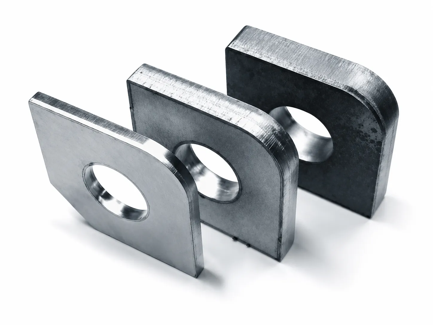
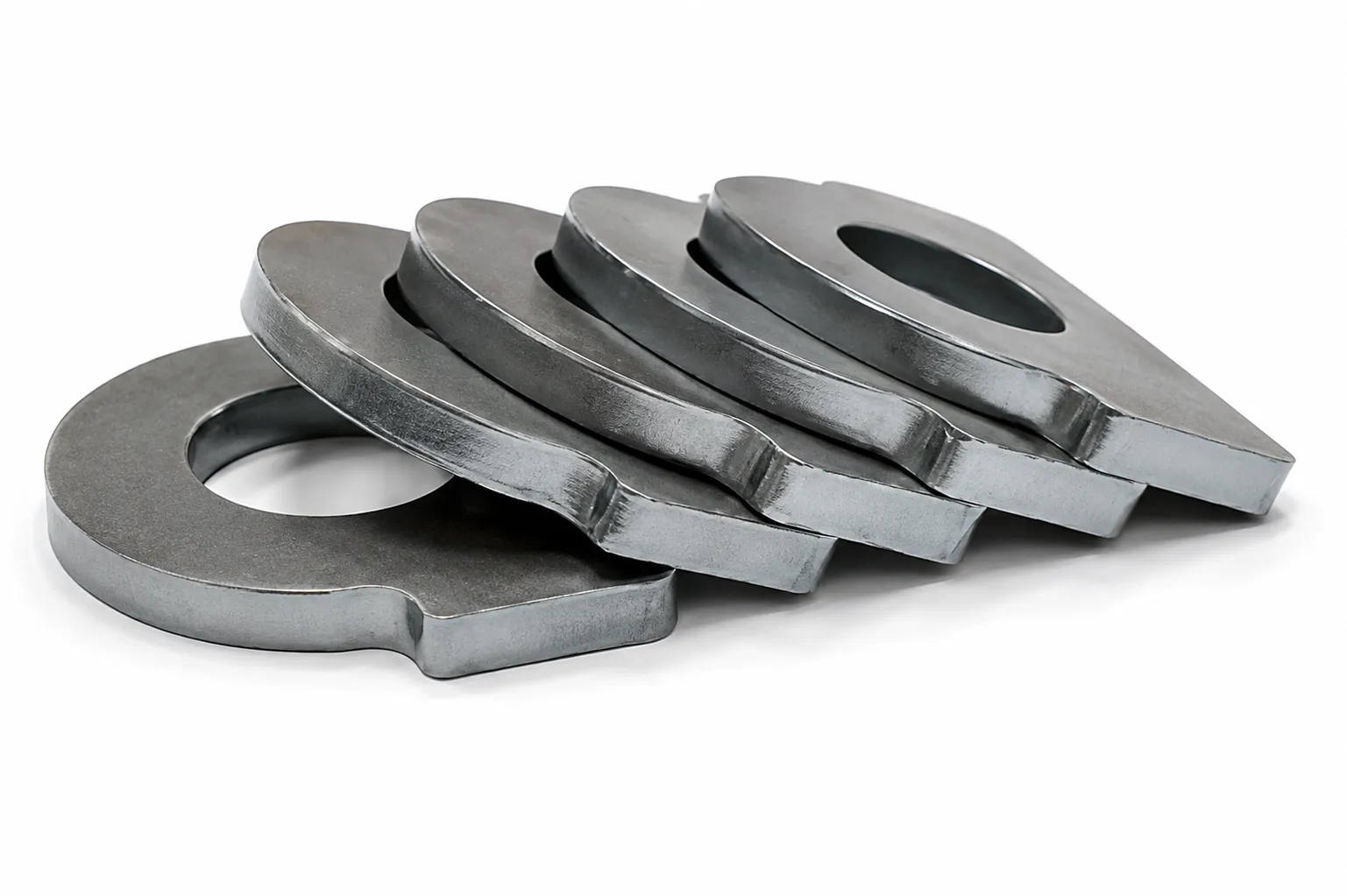
Existing STR gallery references illustrate inspection topics. They are not B trial results, material certificates, thickness labels or proof of the proposed configuration.
State acceptable burrs, dross, discoloration and any later finishing. A bright sample does not establish that a production part meets the requirements for coating, welding or assembly.
Include the smallest recurring hole, slot and narrow feature in the test drawing. Compare actual dimensions and position rather than treating an axis accuracy value as a finished-hole guarantee.
Specify datums, critical measurements and the inspection condition after cutting and cooling. Sheet condition and the part design belong in the evaluation.
Choose multiple positions and repeated features for inspection. Record rejects and rework so the timing result describes acceptable output rather than one selected good part.
| Workpiece | Drawing revision, units, material grade, thickness, surface and nest |
|---|---|
| Configuration | Exact machine, source, head, assist gas and recorded process conditions |
| Acceptance | Critical dimensions, inspection method and edge/hole requirements |
| Cycle boundary | Cutting only, or clearing/loading/exchange as well; good parts and rejects |
| Traceability | Labeled samples, photos, measurements and any unresolved trial items |
The assist gas influences material removal and the edge condition. Select it with the material, laser package and downstream requirement; changing the gas is a process decision, not simply a purchasing shortcut.
| Approach | General process distinction | What to compare |
|---|---|---|
| Oxygen | Reactive cutting uses oxidation of heated metal as an additional energy contribution. | Resulting edge, acceptable surface condition and later finishing needs. |
| Nitrogen | Fusion cutting uses laser energy with nitrogen to eject melt and limit oxidation at the edge. | Edge quality, gas supply and the capability of the proposed configuration. |
| Compressed air | An option only when supported by the offered source, head and process package. | Sample result and complete supply/finishing cost rather than gas price alone. |
No single nozzle, focus or gas pressure suits every sheet. Use the approved process data for the equipment supplied. An attractive gas price can be offset by extra finishing, rejects or supply limitations.
General mechanism references: TRUMPF reactive cutting and fusion cutting. Source-system capabilities and settings are not B specifications.
The right comparison starts with the handling process and required installed protection. These layouts serve different workshop decisions; the table is not a blanket price, safety or productivity ranking.
| Layout | Sheet-flow question | Site/configuration question |
|---|---|---|
| A single-platform | Can loading, cutting and collection share one worktable with acceptable between-cycle handling? | Access, protection and utilities for the single-platform configuration. |
| B open exchange-table | Can the other table be prepared in time, under the approved operating sequence? | Exchange envelope, material routes and site protection around an open layout. |
| BD enclosed exchange-table | How do external handling and the enclosed cutting position work together? | Enclosure/access package, exchange layout, extraction and installation footprint. |
Compare the A single-platform machine or enclosed cutting configurations when the production layout points in another direction.
State the revision, units and scale. Explain open contours, duplicate geometry or intentional connections before the program is prepared. Agree supported file formats and import requirements with STR.
Identify critical holes, datums, narrow features and required tolerances. Include the cosmetic face and any later bending, coating or welding that changes the acceptance task.
Provide normal order quantities, sheet sizes and material mix. Explain whether the trial uses your actual production nest or a mutually agreed representative drawing.
Describe how parts are separated, labeled and moved to the next process. Dense nests or delicate finished faces may change the outside-table workflow.
Plan access and part identification before delivery. Two worktables create two support surfaces to manage, plus an exchange mechanism whose service procedures must match the supplied machine.

Order by the approved head model and part identifier. Coating and dimensions matter; visible similarity is not proof that an optical window fits the supplied system.

Keep an identified stock of approved nozzle and mount parts. Track the supplied head and any authorized changes so replacement orders use the actual configuration.
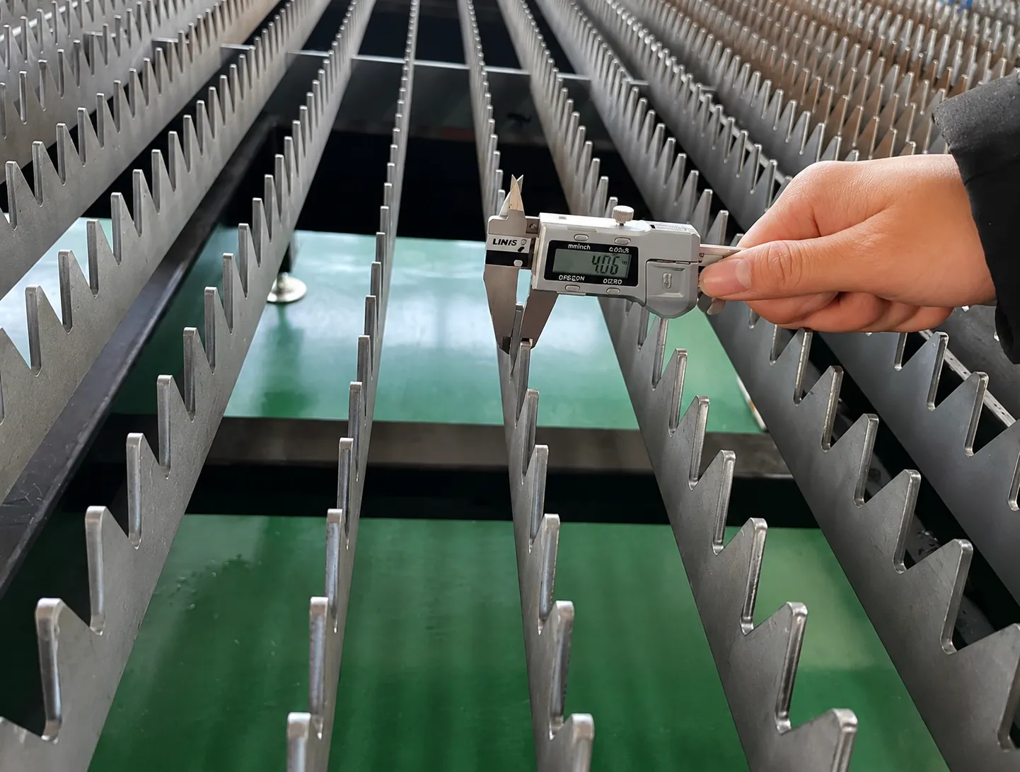
Include both tables in the approved inspection and cleaning routine. Worn or contaminated support surfaces can change how sheets and small parts rest on the bed.
STR library references identify consumable categories only. Image labels, dimensions and pictured part designs are not adopted as B component specifications.
| Area | Plan around the supplied instructions | Useful handover information |
|---|---|---|
| Exchange mechanism | Access/isolation, cleanliness, inspection and lubrication for the actual arrangement. | Operating/service procedure, schedule and approved components. |
| Moving system | Specified care for guides, drives, covers and lubrication. | Service points, consumable identifiers and responsibilities. |
| Extraction/cooling | Filters, duct access, chiller checks and waste handling for the actual material process. | Manufacturer documents, service indicators and replacement parts. |
| Site protection | Inspection of the installed protective arrangements by the required procedure. | Approved operating-zone layout and authorized support scope. |
Obtain a general arrangement drawing of the B system as supplied. Include the exchange-table movement envelope, permitted sheet-loading positions, material staging, people routes and service areas. A long catalog view does not provide a usable floor plan.
Review receiving access, lifting, floor conditions and the placement of the machine and tables. Agree who provides handling equipment and who completes positioning.
Confirm voltage, phases, frequency, connected load and grounding requirements. Include the chiller and other auxiliary equipment in the utility review.
Match supply arrangements to the approved process. Plan ducts, filters, service access and waste handling around the site, not as an afterthought to machine placement.
Review the actual open-layout operation, surrounding access, protective measures and destination documentation before operation. Do not infer compliance from the product image.
An open-layout catalog description does not establish a lower installed cost. Compare the same project scope and required site work before comparing machine prices.
| Stage | Question to close | Record |
|---|---|---|
| Application review | Does the proposed machine and layout fit the recurring parts and site? | Requirements, quoted model/BOM and general arrangement. |
| Representative trial | Do the parts meet quality and agreed timing requirements? | Drawing/material identity, sample measurements and timing boundary. |
| Site preparation | Are handling routes, utilities and protective arrangements defined? | Installation requirements and a clear responsibility list. |
| Pre-shipment check | Does the supplied configuration match the agreement? | Agreed inspection record, packing list and model-specific documents. |
| Site handover | Are the agreed installation, instructions and acceptance items complete? | Results, open items, manuals, parts list and support contacts. |
This is a proposed procurement sequence to agree with STR, not a claim that a trial, inspection or service has already been completed.
A representative drawing, material description and sheet-to-part workflow give the configuration discussion a concrete starting point.
Prepare my B requirementsIt combines an open sheet-cutting layout with exchange tables, separating the cutting position from a position used to prepare the next table. The supplied operating sequence and site protection define permitted access and overlap.
A uses one worktable for loading, cutting and collection. B uses an exchange-table arrangement. Whether the extra handling position benefits the job depends on the recurring nest, outside preparation time and installation requirements.
The B range discussed here has an open cutting layout; BD is the enclosed exchange-table range. Both require configuration-specific evaluation, but their access, protective arrangement and installation tasks differ.
No. The full cycle depends on cutting, clearing/loading, exchange and non-overlapping work. If the outside table is not ready, the next cycle still waits.
No. Moving the table does not by itself load a sheet, remove a skeleton or sort parts. Those functions must be separately identified in the proposal.
Only the loading positions and methods permitted for the installed system should be used. The lifting approach, movement clearances and protective arrangements need a defined site plan.
Supply material grade, routine and occasional maximum thickness, sheet dimensions, part quality and workload. Use a B-specific configuration and trial rather than borrowing another model's values.
Material compatibility requires approval for the offered source, head and process. Send the alloy, thickness and drawing for review; a general fiber-laser material list is not a configuration guarantee.
The main machine image identifies the B range. Separately labeled process, sample and consumable images are general STR references; they do not establish a B capacity, result or bill of materials.
Send country, materials, thicknesses, sheet sizes and weight, a representative drawing, quantities, loading/collection method, available layout, utilities and delivery requirements.
Use these established STR pages to explore alternatives while the B configuration is reviewed.
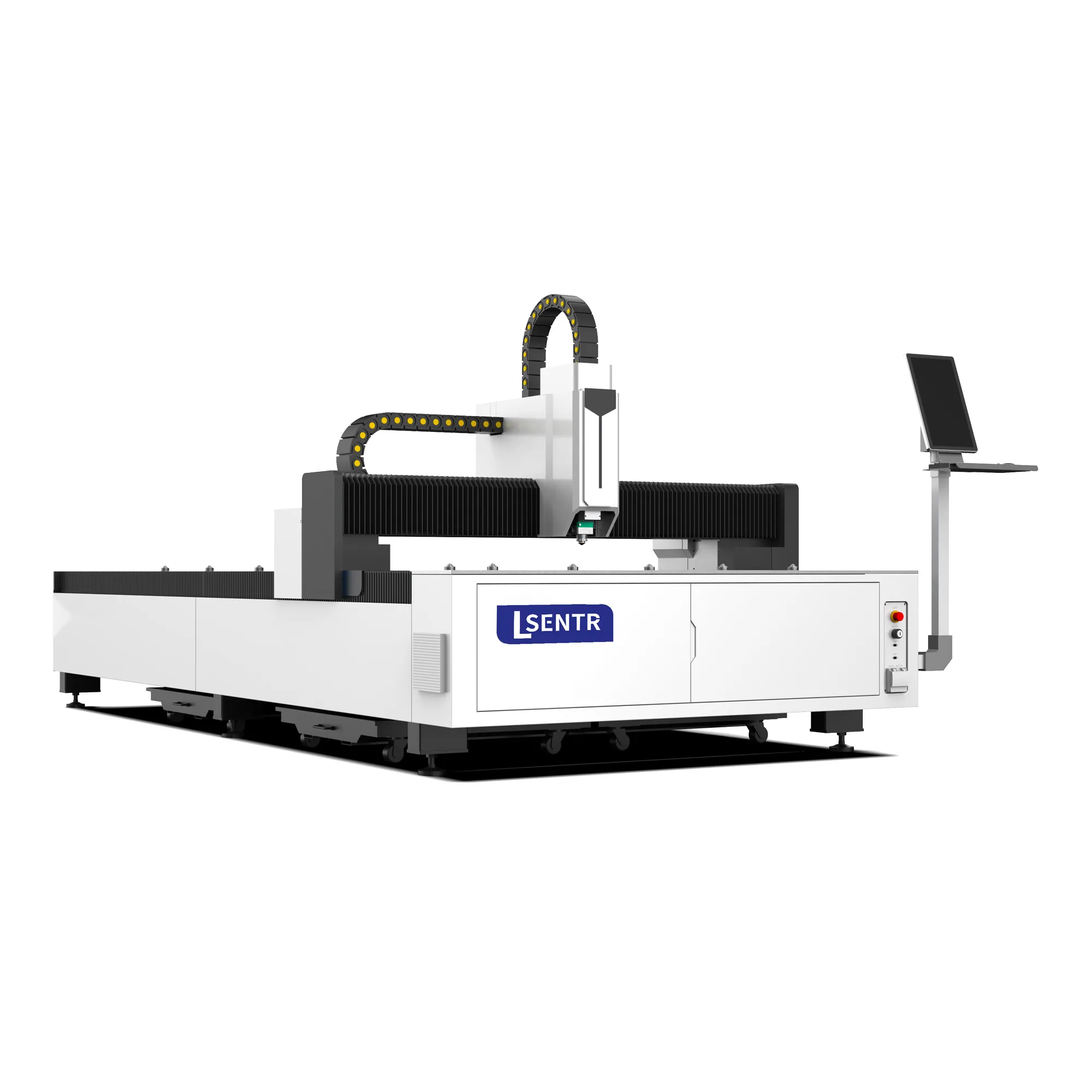
Review a single cutting table when loading and collection can share the same work surface.
View the A machine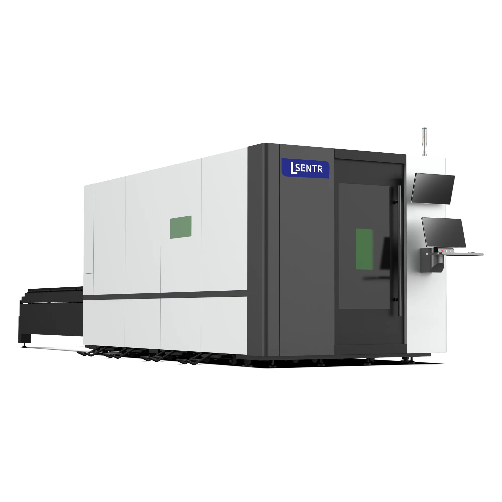
Explore the enclosed layout and how its access and protective package fit the site.
Compare enclosed cutting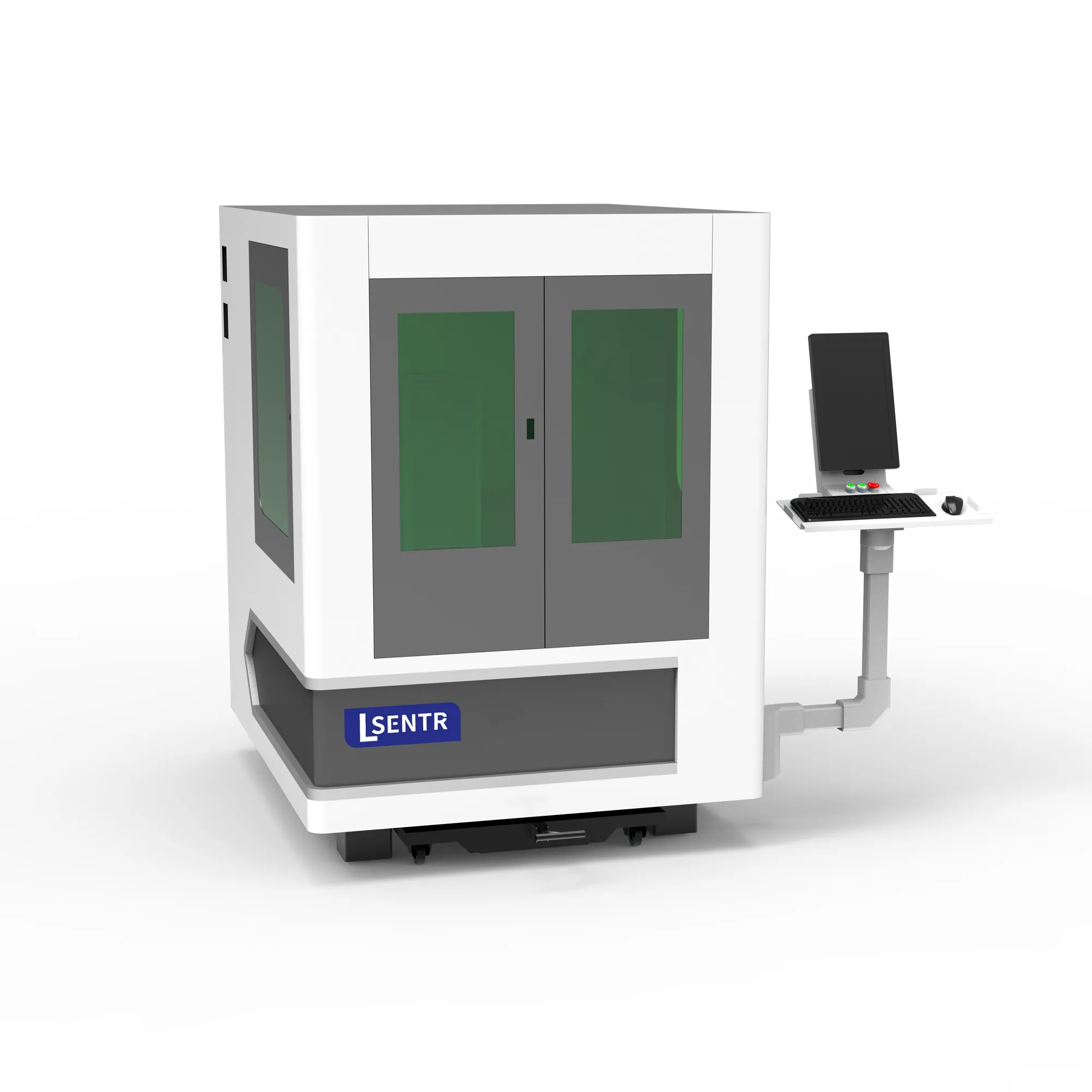
Consider a distinct compact-machine selection for smaller workpieces and fixtures.
View the D rangeBring your recurring nest and describe how sheets arrive, parts are collected and the next table is prepared. Include site access and utilities in the configuration discussion.
Prepare and review your requirements summary, then send it through the STR contact page or email. This form does not submit an inquiry.
Discuss your application with STR. We supply industrial laser cutting, welding, cleaning and press brake equipment for metal fabrication.
Tell STR what you need to cut. We will review the application and discuss a suitable configuration.