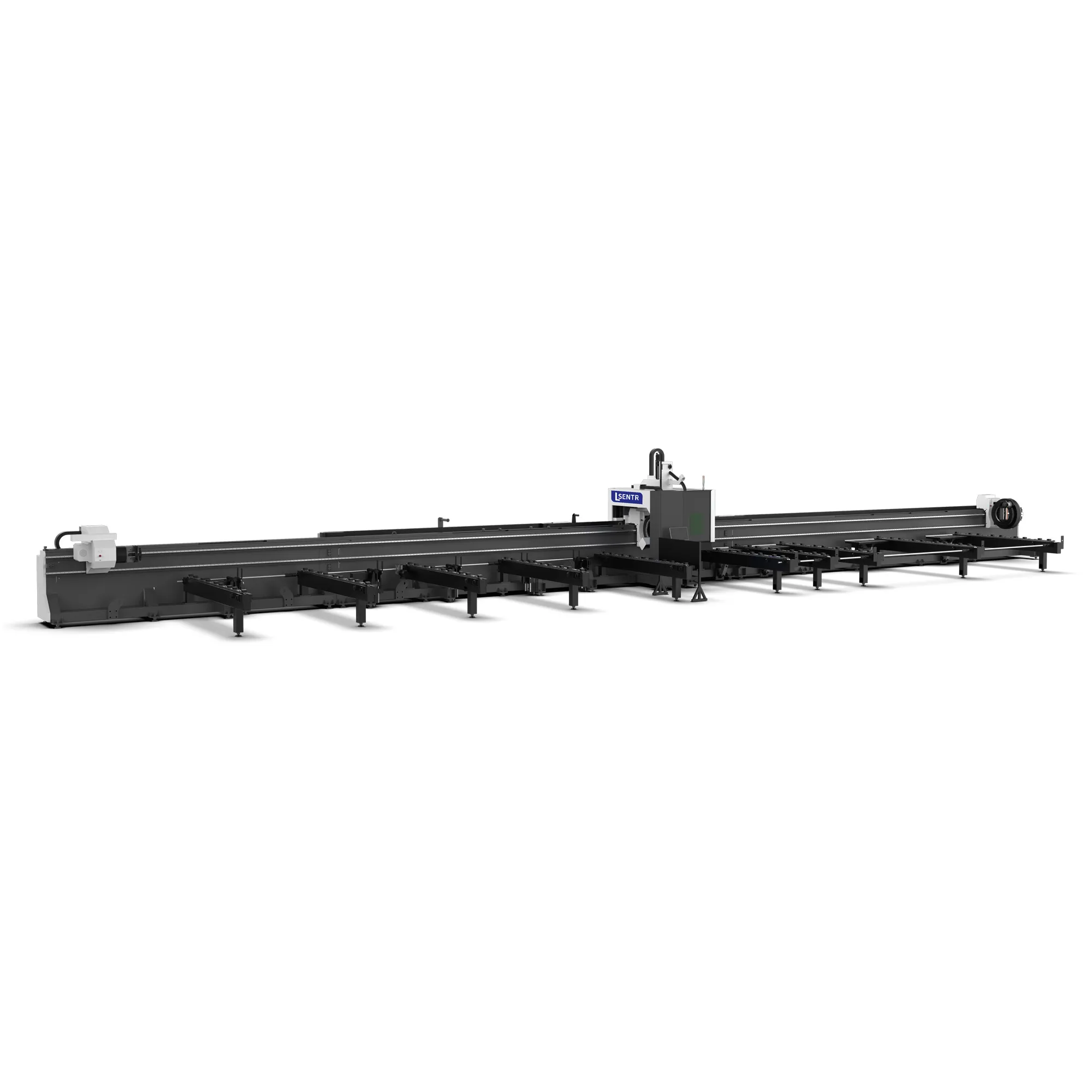
GT Three-Chuck
Review the grip-transfer and support route for tubular components.
Explore GT
STR G-H · Define the section, the accessible features and the supported workpiece.
STR G-H is listed as Heavy H Steel Cutting Type in the STR range. Review the section depth, flange width, separate web and flange thicknesses, beam length and required features together. Match access, positioning and support to the finished part that your fabrication process needs.
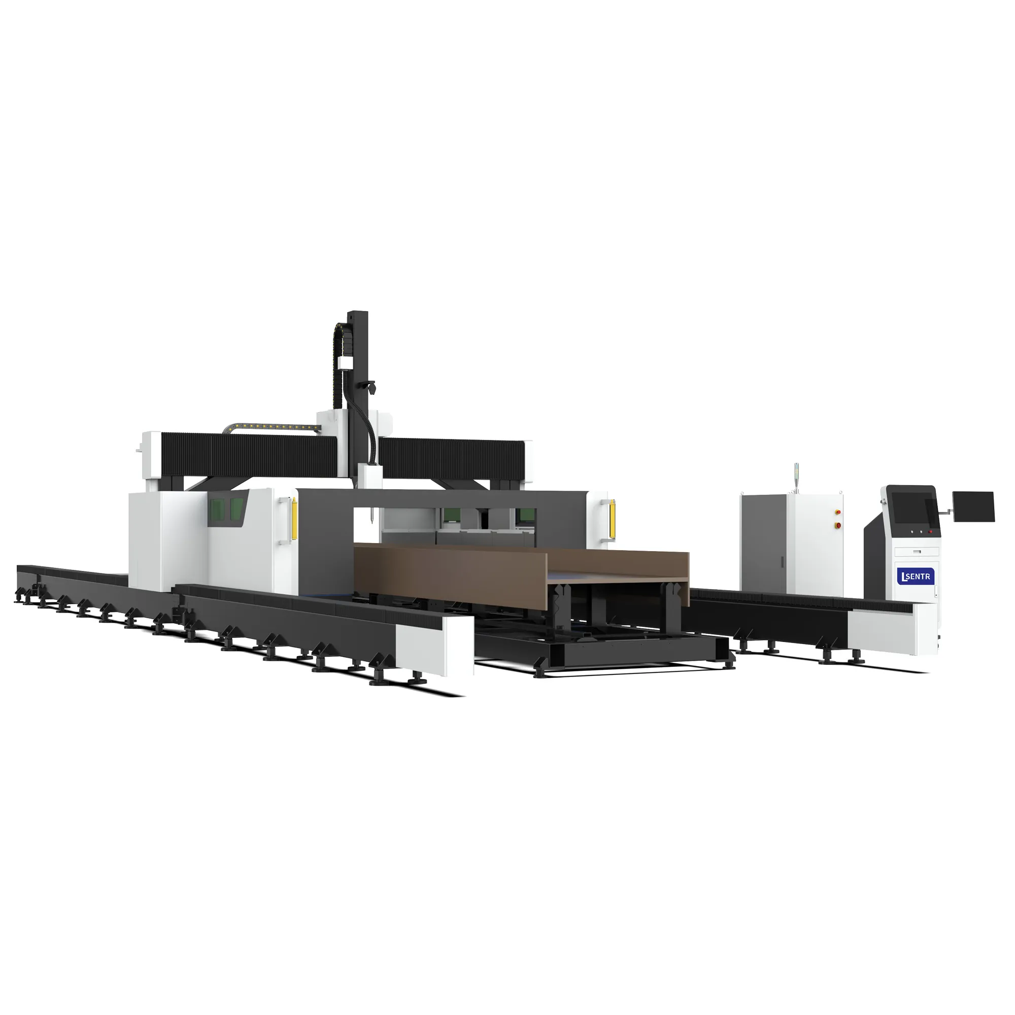
Original G-H catalogue image with labeled details from the same source. Confirm process access, support and handling in the actual offer.
Review the full profile and the features on each face.
Identify the material, rolled or welded section, web/flange thicknesses and stock length. Mark each required hole, opening, end cut or weld-preparation feature.
An H-section presents several faces and different local thicknesses. A useful machine review connects the section drawing to the features on its web, flanges and ends, then establishes how the workpiece is located, supported and accessed through the proposed process.
For beam and column components, supply the required end geometry, hole pattern and connection datums. Review each feature with the offered head, holding method and program.
For recurring members, include section variation, stock identification, setup and part marking requirements. Confirm how each accepted part reaches assembly.
Review actual length, mass, support locations and lifting/collection arrangements. A section-size limit alone cannot define the complete handling capacity.
Match stock, grade and drawing; establish the agreed datums.
Review contact positions and the accessible cutting zones.
Validate face access, local thickness and the actual sequence.
Measure features and prepare the part for the next operation.
Request the G-H technical sheet, installation layout and itemized scope for the ordered revision. Use the required section and connection drawings to qualify the complete process rather than selecting from a single nominal size.
| Item | Definition required in the offer |
|---|---|
| Model and process layout | G-H revision, working arrangement, axes/head, positioning and holding method, cutting zones and service access. |
| Section range | Permitted section types, overall depth, flange width, flange/web thickness, root geometry and incoming condition. |
| Length and mass | Usable stock and finished-part lengths, mass per length, total workpiece mass and load/support conditions. |
| Feature access | Qualified web/flange/end regions, head clearances, repositioning requirements and limitations near roots, fixtures or supports. |
| Cutting system | Source/head, power, gas, cooling, extraction, process data and optional bevel/marking functions explicitly listed. |
| Software and identification | Accepted input formats, detail interpretation, programming/nesting scope, licenses and part identification method. |
| Handling and acceptance | Loading/recovery equipment, site interfaces, representative samples, inspection criteria, training and commercial scope. |
The STR reference establishes the G-H Heavy H Steel Cutting Type identity and rendering. It does not supply verified numeric ranges, axis count, bevel angles, cutting speed, positioning accuracy or load ratings.
Two sections with the same outside dimensions can have different web thickness, flange thickness and root geometry. Send the full section designation and drawing, including the supplied condition and any rolled or welded details that affect the required feature.
Select a region to see the information needed for a configuration review. The schematic explains section terms; it is not a G-H capacity drawing or a verified tool path.
Provide overall depth and flange width together with member length, mass and incoming straightness or twist.
| Feature requested on the drawing | What the application review needs |
|---|---|
| Web or flange holes | Face, size, location, tolerance and datum; sample the actual thickness and surface condition. Confirm whether the laser-cut result meets the required finished hole. |
| End cuts and copes | Complete end geometry across web and flanges, fit-up surfaces and corner conditions. Review head approach, holding and any repositioning. |
| Access holes and notches | Actual root/weld geometry, clearance and permitted final contour. Do not assume a standard outline remains accessible near the web-to-flange junction. |
| Bevels or weld preparation | Required faces, angle, root face and edge condition. Confirm head motion, clearance and sample results; bevel capability is not established by the G-H label. |
| Part identification | Marking location, method and readability after finishing; confirm whether marking hardware/software is included. |
These are feature requests for qualification, not a list of verified G-H functions. A cut on an accessible outer face does not demonstrate inner-face or root-region access. Tie every claimed operation to the offered configuration and a representative sample.
Industry context: Penta Laser’s H-beam product description specifies flange/web processing, control and loading options for its own machine. This illustrates the need to define those scopes explicitly; its axes, angles, software and capacities are not G-H specifications.
Identify support and holding locations for the stock, the changing cut geometry and the released part. Review access around these locations and how the required datums are maintained if the workpiece must be repositioned.
The image shows an H-section on supporting structure. It cannot establish allowable mass, clamp type, automatic support movement or the loading/recovery sequence.
Provide mass per length and total member mass with the actual length. Ask for the permitted support conditions and finished-part handling limits; a nominal section size is not a load rating.
Review fixture/contact positions against the feature list. Identify excluded regions, setup changes and the method used to keep the part located through the sequence.
Confirm how the final cut affects the support arrangement and how parts or remnants are recovered. Include both long members and short offcuts in the proposed route.
Provide the workshop’s stock and finished-part movement plan. Obtain supplier requirements for access, lifting interfaces and site responsibilities from the actual layout.
Record tw and tf separately. Qualify the thickest required local cut and the actual feature geometry with the offered laser/head and gas, rather than using overall beam depth as a cutting-thickness value.
Provide the delivered section drawing, root radii or weld geometry, and expected dimensional variation. Confirm how the proposed setup establishes position and whether any sensing/compensation is supplied.
Identify grade, mill scale, coating and the supplied condition. Agree the preparation and process used in the sample trial, so the demonstration represents production stock.
Define fit-up, edge cleanup, weld preparation and coating needs. Determine any secondary finishing from the accepted sample and drawing; do not assume laser cutting eliminates drilling, grinding or machining in every job.
Supply a section drawing and a complete part or connection drawing with dimensions, tolerances, revision and required marking. A 3D model can clarify face relationships, but confirm the exact input formats and program functions supported by the offered software.
Ask for a trial import of a representative real file. Check units, orientation, web/flange features, end geometry, revision and any information that needs manual preparation.
Review the proposed holding, accessible zones and any repositioning. Confirm the method of checking head/fixture clearance and whether simulation or collision checking is included.
Evaluate stock allocation with actual kerf allowances, end preparation, fixture exclusions and useful offcuts. Do not infer zero waste or a nesting-efficiency figure from the machine image.
Agree the part ID, drawing revision and inspection record carried to the next operation. Confirm any marking or production-data interface as part of the actual scope.
| Reference | Selection focus | Boundary to keep clear |
|---|---|---|
| G-H Heavy H Steel Cutting Type | H-section geometry, web/flange feature access, holding and supported handling. | Confirm the complete process; catalogue appearance does not verify axis count or all-face access. |
| GT three-chuck tube configuration | Tube gripping, transfer and support around the required tubular part. | A chuck-count label is not proof of compatibility with the G-H section and feature envelope. |
| G-A automatic-loading tube configuration | Queued tube stock and repeated feeding. | Tube loading automation does not establish H-beam handling or G-H automation options. |
| Sheet cutting range | Flat components and plates before fabrication. | Cutting separate plates is a different process route from machining a supplied H-section. |
Keep the finished drawing and required incoming material the same when comparing proposals. Other open or hollow profiles require their own application review; the H-steel label does not qualify every profile.
Use representative production stock with an agreed drawing and inspection plan. Record the actual machine revision, source/head, gas, software, fixtures/supports, setup and any repositioning used.
| Trial item | Evidence to record |
|---|---|
| Incoming member | Grade, section designation, h/b/tw/tf, root or weld detail, length, mass and actual straightness/twist condition. |
| Positioning and access | Datums, support/holding locations, reachable regions, setup changes and any excluded features. |
| Web and flange samples | Hole/location/contour measurements, thickness and face tested, edge condition and relation between features on different faces. |
| Roots, end cuts and bevels if quoted | Actual contours, required clearance, fit-up and edge-preparation results; show any required secondary operation. |
| Repeat members | Identifiable samples across repeated setups or members, with drawing measurements and accepted/rejected results. |
| Separation and recovery | Released-part support, contact marks, handling method, remnant condition and operator tasks. |
| Complete job time | Shared timing boundaries for loading, setup, processing, repositioning, inspection, recovery and changes—not isolated cutting speed. |
Include the feature nearest a root, fixture or access limit and the actual local thickness. A demonstration on an easy outer face cannot establish every feature on the connection. The catalogue image is not a sample-cut or load-test report.
Obtain the layout including machine travel, incoming stock, holding/support equipment, finished parts, lifting access, scrap and maintenance clearance.
Confirm site/foundation requirements, electrical input, cooling, gas delivery and extraction for the ordered build. Do not size services from a catalogue rendering.
Review the supplied protective arrangement around cutting, travel and material handling. A housing or gantry image does not establish a laser classification or certification.
Plan member identification, inspection access, remnant storage and transport to welding or assembly. Confirm any automation interfaces and responsibility boundaries.
Follow the actual manual for contact surfaces, fixtures, supports and permitted adjustment. Retain setup records and inspect when marking or dimensional results change.
Use the ordered maintenance schedule for the fitted guides, drives and protective covers. Identify access and replacement items from the delivered BOM.
Specify consumables for the actual head and process. Confirm gas, cooling and extraction conditions along with the inspection/replacement procedure.
Include setup, datum establishment, program identification, approved interruption recovery and backup procedures. Agree service contacts and spare-part references.
Request an itemized offer for the base machine, laser/head, workholding/support, handling, extraction/cooling, software and process options. Include the representative feature trial, measurable acceptance criteria and any secondary operations that remain.
Agree packing, shipping, installation, commissioning, training, documentation, spare parts, warranty conditions and delivery schedule. Compare costs per accepted member using the same stock, drawing, setup, inspection and finishing scope. Avoid inferring a payback period or production rate from the heavy-duty label.
Have the H-section and connection drawings?
Prepare a G-H application reviewSTR identifies G-H as Heavy H Steel Cutting Type. This page covers its H-section application review; the exact supported sections and operations are defined by the ordered technical sheet and sample trial.
Send the section designation and drawing with overall depth h, flange width b, flange thickness tf and web thickness tw, plus root or weld details, length, mass, grade and incoming condition.
List each required face and feature on the drawing. Confirm head access, fixture/support clearances, sequence and any repositioning through the proposed configuration and representative samples.
No. The image shows structure, not an axis specification. Confirm the actual head/axes, usable motion, bevel faces and required edge geometry in the offer and trial.
Submit each profile for a separate review of geometry, holding, support, head access and programming. Do not infer a qualified profile list from the H-steel label.
The usable process depends on section geometry, length, mass, support conditions, positioning and feature access. Obtain all applicable limits for the actual build, including finished-part recovery.
Determine the finished edge, hole and weld-preparation condition from the drawing and accepted samples. Required cleanup or secondary machining depends on the specific feature and production route.
Provide section and connection drawings, material grade, flange/web thicknesses, stock/part lengths and mass, feature locations, batch quantities, file formats, workshop handling and destination.
These tube configurations are separate product references. Their gripping and loading functions are not G-H specifications.
Review the grip-transfer and support route for tubular components.
Explore GT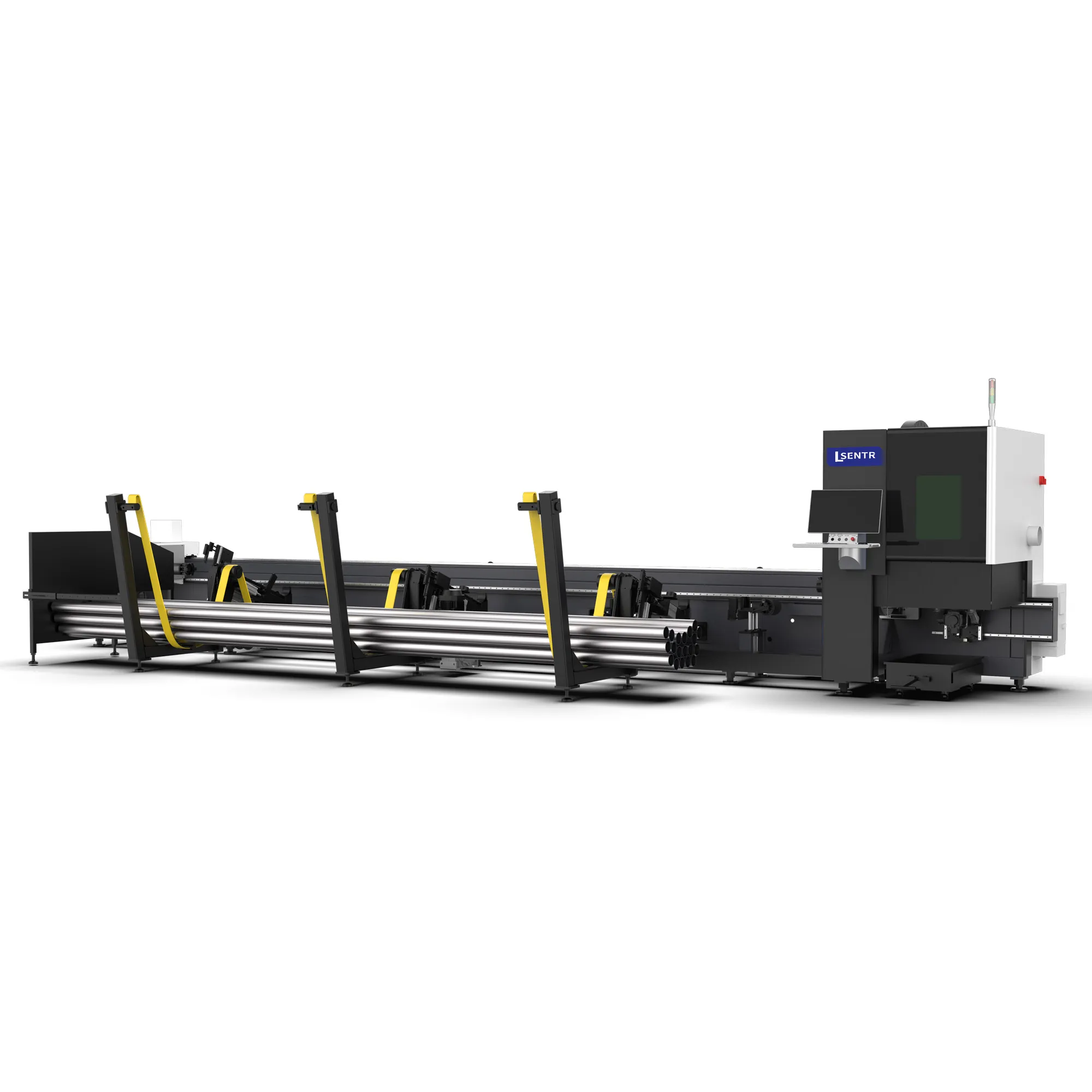
Review stock queues, repeated tube feeding and replenishment.
Explore G-ABring the complete section and required features for an application-specific G-H review.
Prepare G-H requirementsSend the section and connection drawings, grade, flange/web thickness, length and mass. Describe the required feature faces, batch quantities and handling route.
Prepare and review your requirements summary, then send it through the STR contact page or email. This form does not submit an inquiry.
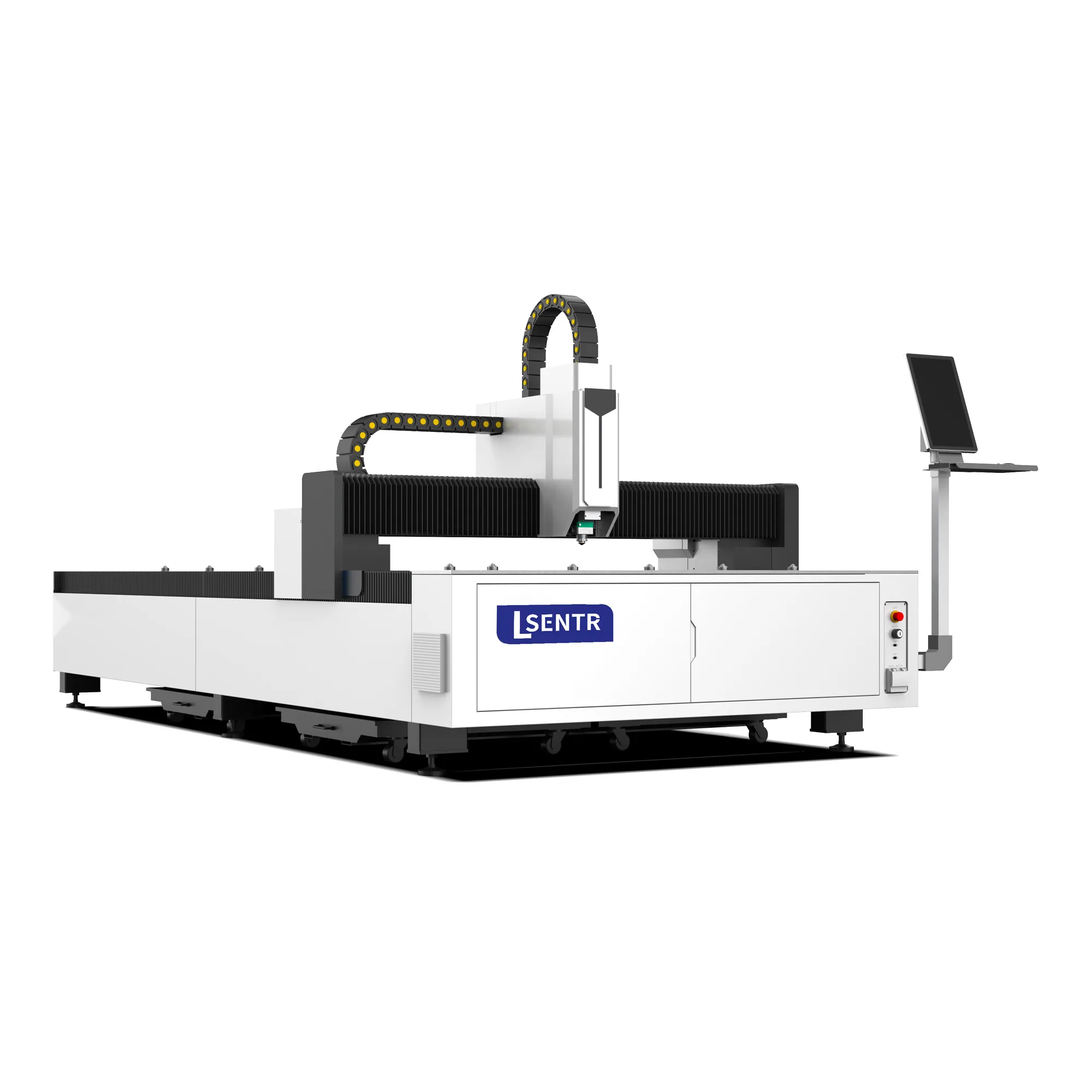
Discuss your application with STR. We supply industrial laser cutting, welding, cleaning and press brake equipment for metal fabrication.
Tell STR what you need to cut. We will review the application and discuss a suitable configuration.