
Fiber laser source
Confirm model, rated output, operating conditions, electrical input, cooling requirements and service scope. A file name or photographed cabinet does not verify the installed power.

STR A High Power · Match the laser package to your production plate mix.
The STR A High Power page focuses on the laser and process configuration for metal plate cutting. Start with the material and thickness you cut most often, the required part quality and the complete production route. A useful power choice must work with the head, gas, cooling, machine structure and workshop supply.
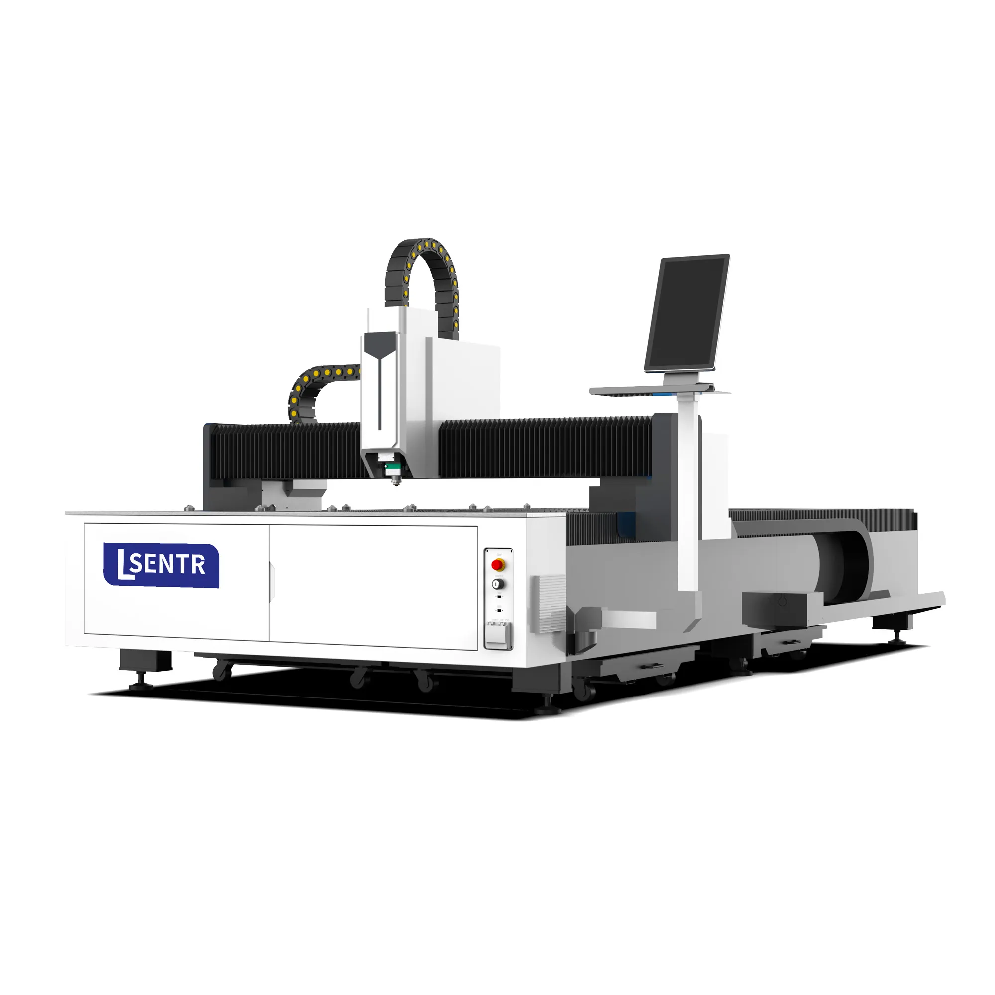
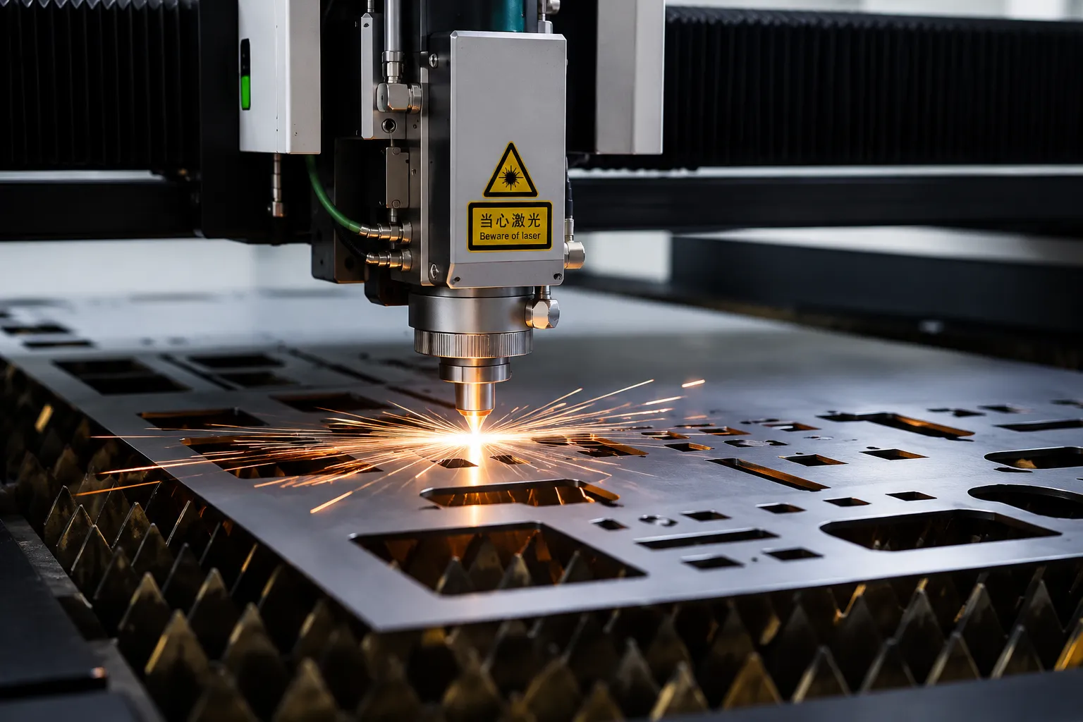


Original references published on the high-power A page. The A-series machine illustration does not identify its installed power or full supplied configuration.
Application-specific laser configuration for sheet and plate production.
List material grades, usual and maximum thickness, sheet size and parts per shift. Include one representative nest and the downstream edge requirements.
High power describes the laser-output configuration. High acceleration describes how the motion system changes velocity. They can coexist in one machine, but neither term establishes the other. The complete package and the cutting task determine the useful result.
| Page / configuration focus | Start the review with |
|---|---|
| A High Power | Material and plate thickness, piercing, edge condition, process resources and accepted batch output. |
| AG motion configuration | Short moves, repeated direction changes, contour quality and the measured complete cycle. |
| Standard A | The ordinary material mix, single-platform workflow and the required laser/cutting package. |
Do not choose a power level from an acceleration label, or assume a high-power package is automatically the quickest on every nest. Identify the actual process limitation first.
Record which grades and thicknesses occupy most production hours. Occasional maximum-thickness requests should be reviewed separately from the everyday job that determines operating cost.
State the dimensions, cut surface and finishing scope needed for the next operation. Faster cutting only helps if usable parts reach that stage consistently.
Review the source, cutting head, control, machine bed, utilities and plate handling together. A source rating on its own is not a complete machine specification.
The existing STR page lists a range of power and working-area references. Select the actual combination through a dated technical offer and application trial, rather than assuming every listed option is available in every build.
| Item | Published reference or required confirmation |
|---|---|
| Series reference | STR A High Power; identify the exact ordered model in the offer. |
| Published laser options | 12, 20, 30, 40 and 60 kW; confirm the proposed source and compatible machine/head package. |
| Published work areas | 3050 × 1530, 4000 × 2000, 6000 × 2000 and 8000 × 2000 mm; confirm the selected layout and usable envelope. |
| Routine cutting range | Define by material, grade, thickness, gas, contour and acceptance result; request a representative test. |
| Plate support and loading | Confirm distributed/point-load limits, sheet condition, loading method and part recovery. |
| Head and programming | Specify optical/power compatibility, focus/height control, piercing functions, nesting and included licenses. |
| Utilities and auxiliaries | Confirm electrical input, chiller, gas supply, extraction and the complete installation drawing. |
| Acceptance and handover | Agree samples, measurement conditions, repeat run, training, documentation and support scope. |
* Power and area references are taken from STR's existing high-power A page, reviewed 22 October 2026. They are not a verified capacity chart or a confirmed offer. Numerical speed, accuracy, acceleration and maximum-thickness claims are not adopted as current guaranteed specifications. Final combinations and production conditions require technical confirmation.
Prepare a thickness distribution with the approximate share of your work. Add material grade, surface condition, critical features and required output. This makes the comparison specific enough to test and prevents a rare separation cut from defining the whole investment.
This is the material range you expect to process repeatedly with the agreed edge condition and cycle. It should be supported by a representative nest and repeat samples.
State the permitted speed, feature restrictions and finishing for those jobs. Cutting through a plate once does not prove a stable, economical daily process.
Include the smallest required holes, slots, corner radii and narrow webs. An external straight-edge sample cannot establish their quality or dimensional result.
List grades, thicknesses, blank sizes and usual batch quantities.
Define dimensions, edge condition and permitted finishing.
Review the source with head, gas, cooling and control.
Record accepted parts, resources and the complete route.
The laser introduces heat at the cutting point, while the gas route and nozzle help remove material from the kerf. Focus position, optical condition, material, feed and support also influence the result.
Increasing power does not justify multiplying every cutting speed or thickness by the same factor. The proposed settings must preserve the required edge and features on the real workpiece.
Oxygen can contribute reaction energy when cutting suitable steel. Review the resulting edge condition and any oxide-removal requirement before welding, coating or another downstream operation.
Nitrogen or another appropriate inert gas is used in fusion-cutting routes to expel molten material without oxygen's reaction contribution. Specify the required edge and verify supply capacity for the selected process.
Do not treat these as automatic substitutes for another gas. Confirm equipment compatibility, gas quality, material suitability and the accepted edge result before comparing operating cost.
Review focus/height control, nozzle alignment and the supplied inspection procedure. Changing the source power does not correct a damaged or unsuitable optical/gas arrangement.
General process background: TRUMPF's laser cutting explanation describes focus, cutting gas, laser power and feed as process variables. It does not establish a STR cutting table or included proprietary function.
A thick-plate trial needs more than a long straight cut. Piercing, starts, corners, nearby features and repeated cuts can expose problems that a selected sample edge misses.
Inspect the pierce area, spatter, lead-in position and transition into the finished contour. Confirm the offered piercing functions and how the program keeps start damage outside controlled surfaces.
Include dense features and the actual spacing used in production. Review local heat, part stability and cutting sequence rather than predicting the nest from isolated test coupons.
Compare early and later parts after the agreed operating conditions are established. Record interruptions, optics checks, gas/cooling condition and any additional cleanup.
Include the inspection and recovery procedure after a stop or poor cut. Any automatic detection or resume function must be confirmed in the offered control package.
Choose sample locations before testing. If the process is changed during the run, retain the settings and identify which samples correspond to each condition.
These references are published on the existing high-power A page. The actual offer should identify the source, head, controller, mechanics and auxiliaries as a compatible package; the photographs are not a bill of materials.
Confirm model, rated output, operating conditions, electrical input, cooling requirements and service scope. A file name or photographed cabinet does not verify the installed power.
Match the head and optical path to the proposed source and process. List compatible consumables, focus/height functions and the actual maintenance procedure.
Review nesting, piercing, path planning, parameter management and operator recovery. Confirm included software, licenses and training; a screen does not prove every option is supplied.
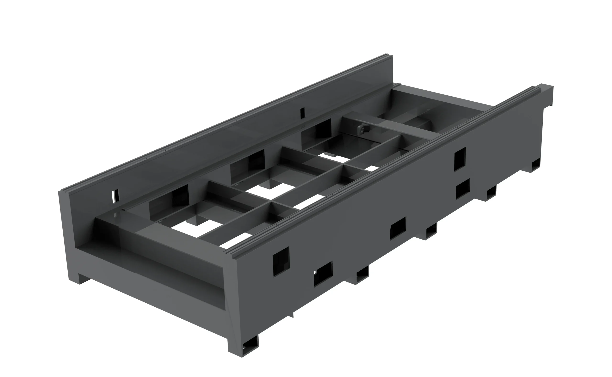
Ask how the offered construction, support, heat exposure and slag handling suit the selected process and load. Confirm inspection and installation requirements without inferring a lifetime from the picture.

Review the moving assembly, alignment and maintenance with the required contour quality. Material grade, treatment and measured motion performance need technical evidence.

Confirm supplied parts, lubrication, protection from debris and service access. Do not derive brand, origin, precision or service life from an unverified component illustration.
| Work material | Information for the application test |
|---|---|
| Carbon and structural steel | Grade, thickness, scale/rust condition and intended welding, coating or machining. Agree oxide, dross and dimensional acceptance. |
| Stainless steel | Alloy, surface/cosmetic requirements, protective film and required edge. Review the proposed gas route and handling. |
| Aluminum alloys | Exact alloy and condition, thickness and smallest features. Confirm source/head compatibility and the required cut result. |
| Copper, brass or other alloys | Request explicit application review for the exact material and package. Steel test results cannot establish suitability. |
| Coated or unusual stock | Identify coatings and material information for process and extraction review before cutting. |
The same nominal thickness can give different results with different grades, surfaces and features. Keep the trial material representative of what your workshop receives.
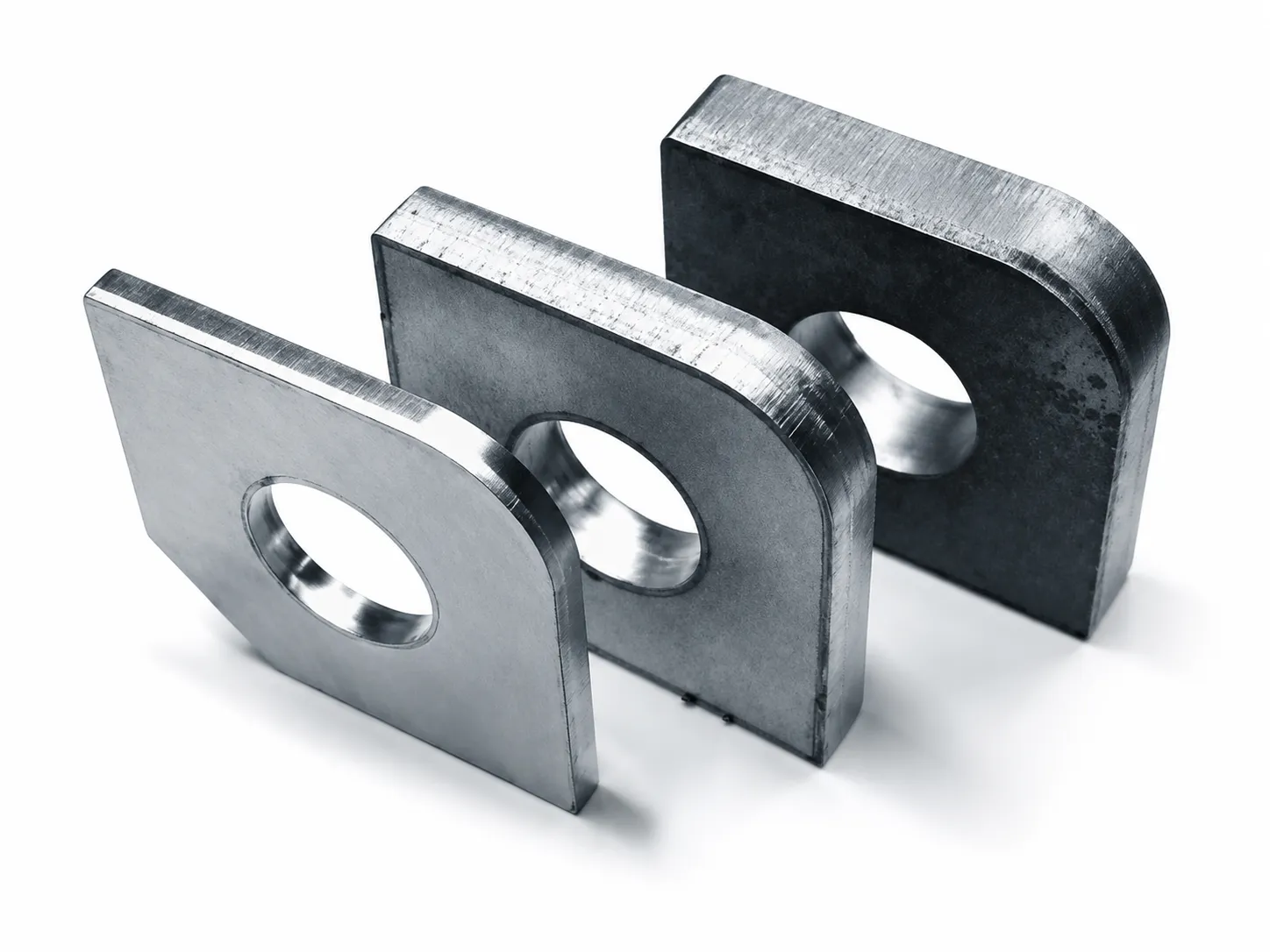
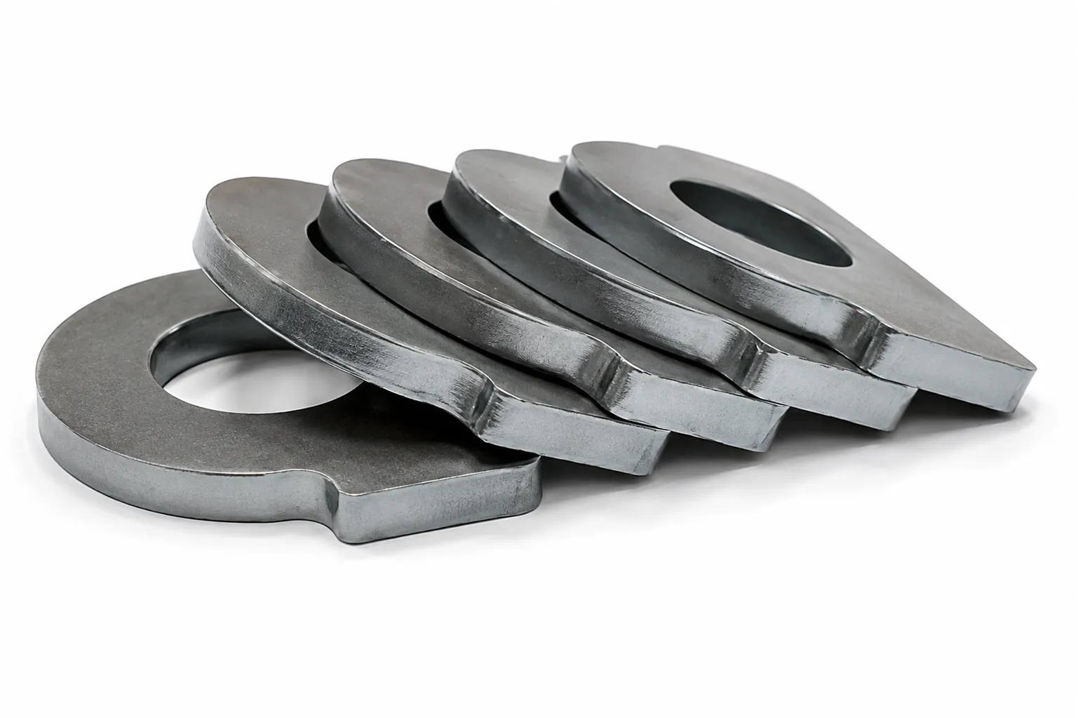
Original sample references from the existing page. The photographs do not verify material grade, dimensions, source power, gas, speed or an accepted high-power A trial.
Use a drawing revision and an agreed material lot. Record measured thickness, surface condition, source/head/control build, gas route, process settings and machine condition. Label the sample and measurement locations.
Include production holes, slots, corners, long edges, start/end regions and a repeated nest. Record actual cutting, piercing, handling, finishing and inspection time, plus rejected parts.
| Acceptance feature | What to define and inspect |
|---|---|
| Part dimensions and holes | Drawing datums, controlled sizes, measurement method and required top/bottom checks through the plate thickness. |
| Edge geometry | Required squareness/taper and surface condition with agreed tolerances and measurement locations. |
| Starts, corners and dense features | Pierce/lead-in influence, local defects, shape and consistency at transitions. |
| Finishing and downstream use | Permitted dross/oxide removal, fit-up, welding, coating or machining preparation. |
| Repeated production | Accepted part count, conditions across the run, interruptions, rework and the complete cycle. |
Working area and load capacity answer different questions. Confirm permissible distributed load, local support, loading impact and the workshop's lifting route with the selected machine. Do not infer a table load from its dimensions or laser power.
Assume a solid rectangular plate 3.0 × 1.5 m and an illustrative density of 7850 kg/m³. Mass = length × width × thickness × density.
| Assumed plate | Calculated mass |
|---|---|
| 3.0 × 1.5 m × 20 mm | 706.5 kg |
| 3.0 × 1.5 m × 40 mm | 1413.0 kg |
These inputs are hypothetical, not a STR load rating, certified material density or cutting-capacity claim. They omit attachments and all handling effects. Use the actual plate data and an approved loading plan; the example does not select lifting equipment.
Review full plate, remnant and finished-part handling. Include loading access, support condition, removal of heavy skeletons and safe service access in the complete workshop layout.
A laser's output rating describes optical power, not the electrical demand of the entire cutting installation. Request input and utility data for the source plus the machine and auxiliaries; do not size the site supply from the optical kW figure.
| System | Confirm in the offered installation data |
|---|---|
| Electrical supply | Voltage/frequency, input ratings, starting/peak conditions, protection, grounding and installation responsibility. |
| Cooling | Matched chiller, heat rejection, ambient limits, water specification, space and service clearances. |
| Assist gas | Required quality, pressure and flow at the machine under load, supply mode, pipework and continuity for the intended job. |
| Compressed air, if used | Required quality/treatment, available flow and equipment compatibility; do not substitute an unverified shop-air connection. |
| Extraction and debris | Configuration for material/process, ducting, collection and cleaning access; identify what is supplied and site-provided. |
| Work area and access | Full machine/auxiliary footprint, loading route, supplied guarding and the local installation assessment. |
The illustration shows an open A-series arrangement. A source-power option does not establish a protective enclosure, laser class or market compliance. Agree the actual safeguarding and installation scope for the receiving site.
Use total batch cost divided by accepted part count. Record how you allocate material, electricity, gas, labor, consumables, maintenance and machine ownership. Include handling, inspection, finishing and rework consistently for both routes.
| Illustrative case | Batch cost, arbitrary units | Accepted parts | Cost / accepted part |
|---|---|---|---|
| Route P | 120 | 30 | 4.00 |
| Route Q, intended result | 156 | 40 | 3.90 |
| Route Q, fewer acceptable parts | 156 | 30 | 5.20 |
All costs and counts are invented inputs for arithmetic, not STR prices, power-level comparisons or production forecasts. The final row holds the assumed batch cost constant only to show the denominator's effect; real rework can change cost too. This example does not prove a payback period or return on investment.
A higher-power proposal should earn its place through the tested workload, accepted output and total operating scope. Compare actual data before assuming that either the lowest purchase price or the highest output rating is the economical choice.
Review thickness mix, locating holes, mounting profiles and downstream machining or welding. Mark the dimensions that determine fit.
Use a normal batch to inspect early/later edge quality, handling and sorting. Include consumable checks and permitted finishing in the record.
Check both the routine thinner jobs and the heavier plate work. Establish whether power, motion, piercing or handling is the limiting task for each family.
High power alone does not supply a bevel arrangement. Send joint sections for the AP bevel cutting review when an inclined edge is required.
Use the correct parts and supplied inspection/cleaning procedures. Record contamination, damage and changing cut results; do not assume a universal replacement interval.
Follow the specified water, filter and gas-quality requirements. Include condition checks and service access for the matched auxiliaries.
Inspect supports, debris collection, extraction paths and protection of guides. Plan cleaning around the material and operating duty.
Keep parameter, inspection and maintenance records. Confirm spare-part identification, remote/on-site responsibilities, training and warranty exclusions in the actual agreement.
Source output does not establish consumable life, maintenance-free operation or uninterrupted production. Intervals, parts and support commitments need the supplied manual and contract.
The technical offer should connect the selected power and work area to the process trial, utilities and handover scope. Before ordering, reconcile any differences between the website reference, proposal and sample report.
Have the material mix, drawing and available utilities ready?
Prepare a high-power A inquiryNo. High-power A focuses on the laser/process configuration; AG focuses on motion response and contour-dependent performance. The characteristics can coexist, but one does not establish the other. Compare the offered build against your actual nest.
Provide your normal material/thickness mix, maximum occasional jobs, critical features, required edge and output. Compare the compatible source/head/gas/cooling package through representative trials rather than selecting from maximum thickness alone.
Request a dated application-specific test for the exact material, power, head, gas and geometry. Distinguish a separation cut from repeatable production with an accepted edge and cycle. This page is not a verified universal thickness chart.
No fixed ratio applies across materials and contours. Focus, gas, material, piercing, quality limits and handling influence the result. Compare complete production records under stated conditions.
No. Obtain input ratings and installation requirements for the source, machine, cooling and other auxiliaries. The optical output alone cannot size the workshop supply.
Confirm the permissible load and support conditions as well as dimensions. Review the real plate mass, loading method and handling route with the selected machine and receiving site.
Cleanup depends on the actual cut and downstream requirements. Agree dross/oxide, surface and fit criteria, then include permitted finishing in the sample acceptance and cost comparison.
Send material grades and thickness distribution, blank dimensions, a representative drawing/nest, required edge inspection, output and workshop location/utilities. Include your current process if you want to compare total cost per accepted part.
Power selection and plate handling should support the same production plan.
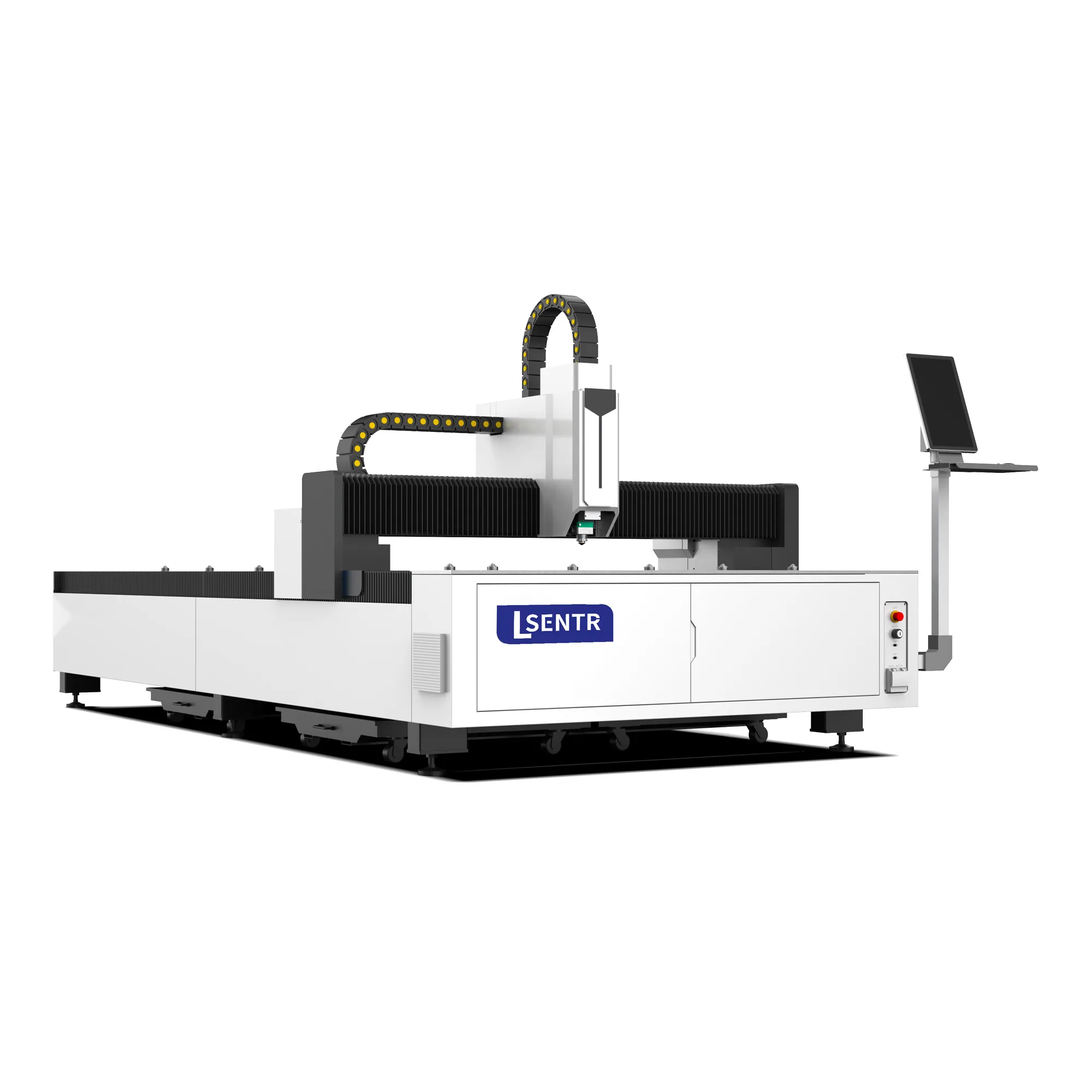
Review the ordinary material mix and a standard single-platform configuration.
View standard A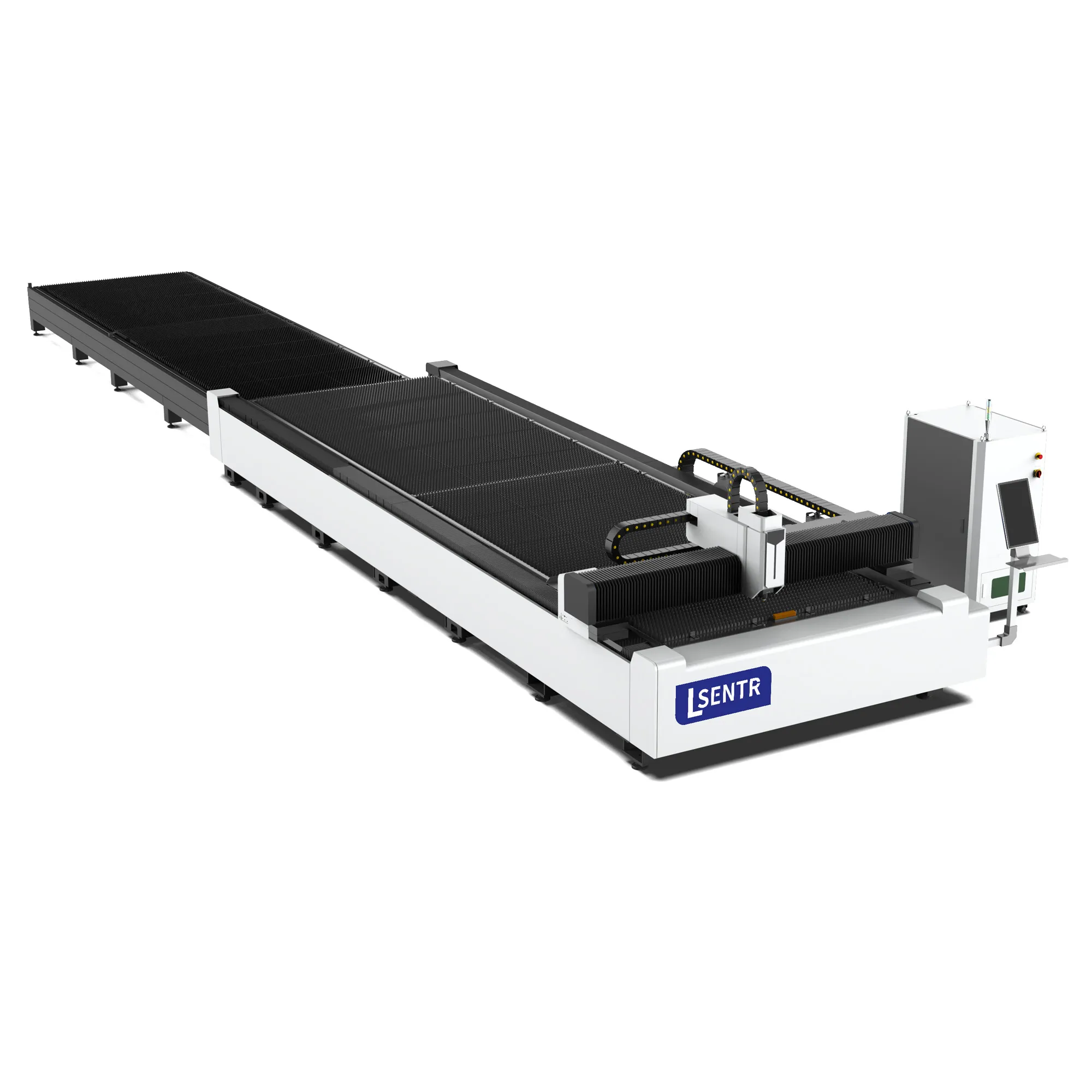
Review sheet preparation, exchange travel, loading and part recovery.
View the B layout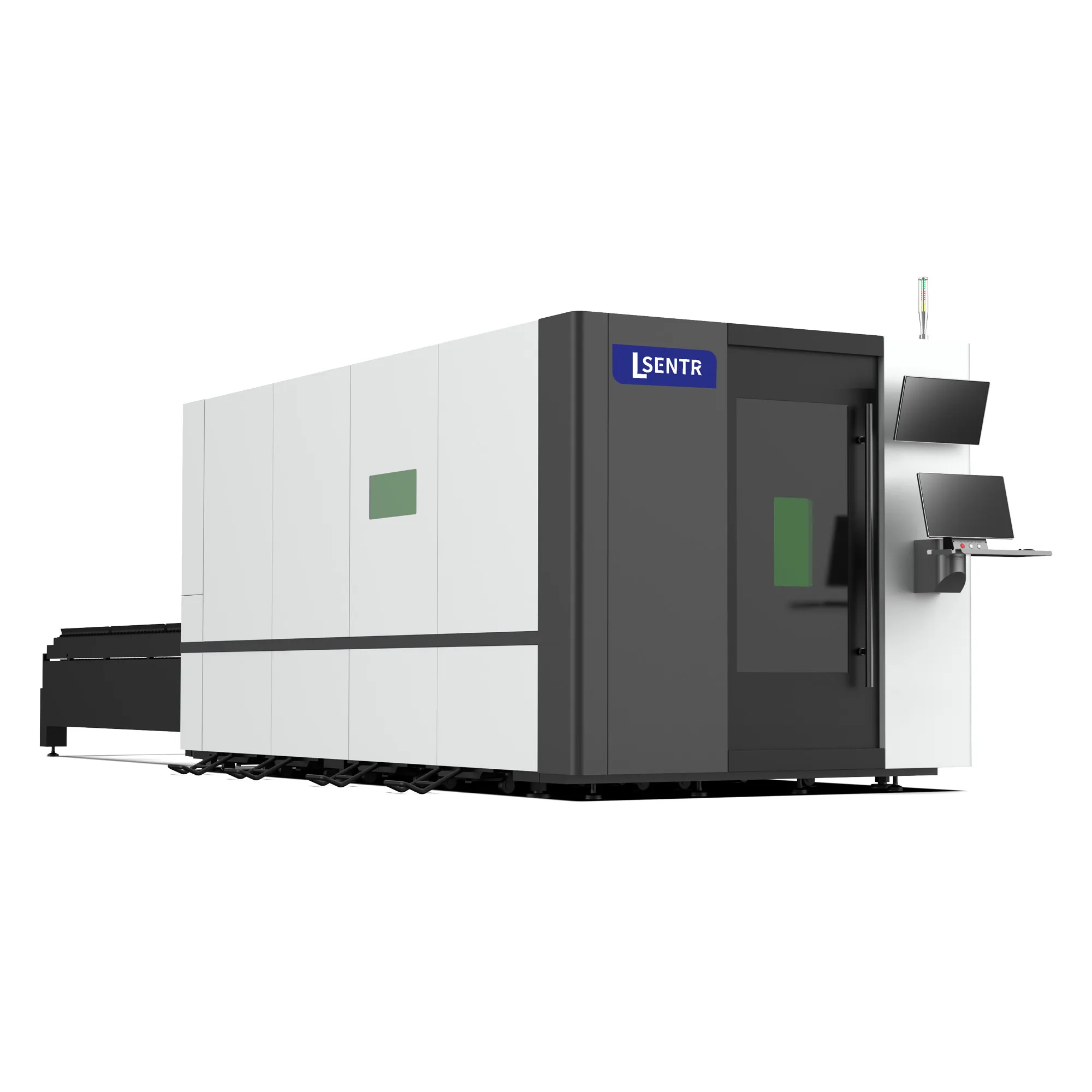
Compare enclosed cutting access with outside preparation and the supplied protection package.
View the BD layoutSend your material grades and thickness mix, a representative nest and required edge condition. Include daily output, plate handling and the available electrical, gas and cooling supply.
Prepare and review your requirements summary, then send it through the STR contact page or email. This form does not submit an inquiry.
Discuss your application with STR. We supply industrial laser cutting, welding, cleaning and press brake equipment for metal fabrication.
Tell STR what you need to cut. We will review the application and discuss a suitable configuration.