Long panels and plate profiles
Compare the one-piece outline, stock availability, datums and recovery method. Any change to a joined design requires the buyer's drawing approval.

STR BG · Plan the cutting envelope and the complete plate-handling route.
STR BG is the open large-format series in the STR catalogue. Review it when long or wide metal parts, larger stock or the proposed nest need a different working envelope. Match that envelope with support, loading, cutting quality and workshop access before choosing the final configuration.
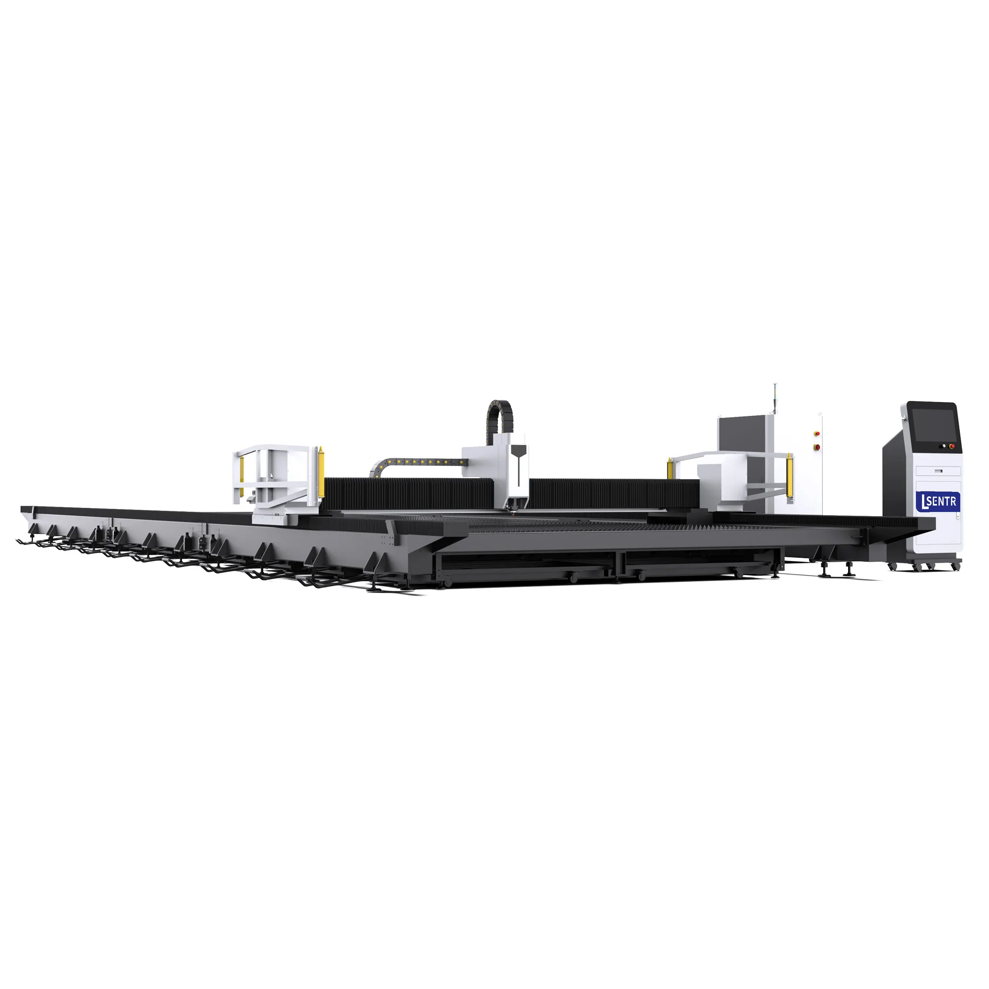
Original BG catalogue image with clearly labeled detail crops. These views do not establish dimensions, installed components or measured performance.
Open-format sheet and plate cutting reviewed around the workpiece and handling plan.
Include blank dimensions, material grade, thickness, critical datums and the available loading route. Mark any part that must remain one piece.
A larger cutting envelope can change which parts and stock arrangements you can process. It also changes the space, support and handling questions. The useful comparison is the complete route from delivered plate to accepted parts, not table area alone.
Identify drawings that require an uninterrupted profile. Check the usable envelope and handling route for that part; do not assume a longer machine removes every joining or finishing operation.
Bring the stock formats your supplier provides and the typical order mix. Extra width or length is valuable only when the parts, quantities and material rules can use it.
Include plate staging, loading, removal, sorting and cleaning in the comparison. A larger nest can shift work into handling even when it reduces the number of blanks.
List purchased formats, largest parts and normal batches.
Allow for edge conditions, support and process clearances.
Trace loading, cut-part and skeleton removal routes.
Inspect the relevant features across the required envelope.
The current STR catalogue identifies BG as an open large-format series. It does not provide a verified BG dimensional, load or cutting-capacity table. Request the following information for the proposed build rather than applying another series' specifications.
| Item | Required definition |
|---|---|
| Series and exact build | STR BG; specify the ordered model and configuration revision in the offer. |
| Usable working envelope | Length, width, permitted stock overhang and restrictions near supports or other obstructions. |
| Installed layout | Full machine, console, auxiliaries, ducts and loading/service clearances. |
| Load and support | Permitted distributed/point loading, support arrangement, blank condition and loading method. |
| Laser and cutting package | Source, head, control, gas and cooling selected for the agreed material/thickness mix. |
| Motion and geometry | Offered axis arrangement, measurement conditions, alignment and finished-part acceptance. |
| Handling and extraction | Access, plate/part recovery, scrap collection and the proposed extraction configuration. |
| Supply and handover | Included software, auxiliaries, installation, training, documentation and service scope. |
BG identity and layout reference: STR's public fibre-laser catalogue, reviewed 22 October 2026. Numerical working areas, laser options, speeds, load limits and tolerances are intentionally left to the BG-specific technical sheet and application review.
Give length, width, thickness and incoming condition. Include the range of real stock sizes, edge condition and flatness expected from the supplier.
Confirm where the process can produce the required features. Machine travel alone does not account for edge margins, head clearance, supports or any restricted region.
Include its full outline, datums, internal features and required recovery path. A part can fit geometrically yet still be difficult to support, inspect or remove.
Use a dimensioned drawing with the source, chiller, gas/extraction equipment, controls and service access. This is larger in scope than the advertised work area.
Ask for these dimensions on one coordinated layout. If a proposal includes multiple working zones, extensions or special loading arrangements, confirm their actual configuration and operating restrictions rather than assuming them from the long bed image.
A simple rectangular example shows why stock format needs the real part mix. Assume identical 2600 × 1400 mm rectangular parts, a fixed orientation, a 20 mm margin at every stock edge and a 10 mm gap between parts. Compare hypothetical 6000 × 2000 and 6000 × 3000 mm blanks.
| Result under the stated assumptions | 6000 × 2000 blank | 6000 × 3000 blank |
|---|---|---|
| Rows × parts per row | 1 × 2 | 2 × 2 |
| Total rectangular part area | 7.28 m² | 14.56 m² |
| Part area / full blank area | 60.7% | 80.9% |
Two parts need 2 × 2600 + 10 + 2 × 20 = 5250 mm in the long direction. Two rows need 2 × 1400 + 10 + 2 × 20 = 2850 mm across the width. Area ratio is part count × 2.6 × 1.4 divided by blank area. This is not an optimal nest, yield guarantee or cost forecast. It omits cutting compensation, lead-ins, defects, grain restrictions and process/support constraints; rotation is not evaluated.
Use the example to ask which extra dimension your real nest can use. Compare the purchased-stock price, remaining usable material, processing route and handling effort before deciding that more table area improves the economics.
Trace each material state: delivered blank, positioned plate, separated parts and the remaining skeleton. They can require different access, support and movement. Include the heaviest and least rigid relevant pieces, not just the original sheet.
| Stage | Questions for the layout and operating plan |
|---|---|
| Stock staging | Where do blanks wait, and how are grades/lots identified without blocking the work area? |
| Loading and positioning | What access and support does the selected method need? Confirm permissible machine loading conditions. |
| Cutting and part release | How do the sequence, remaining supports and thermal condition keep the work stable? |
| Large finished parts | How are long/slender parts supported, removed and moved to inspection or the next station? |
| Skeleton and remnants | How are remaining material and scrap cleared, separated and stored for possible reuse? |
| Cleaning and service | Can the relevant areas be reached under the supplied isolation/maintenance procedure? |
An open bed does not establish unrestricted access during cutting. Confirm the supplied protective arrangement and the approved operating method. Do not assume simultaneous cutting and loading, independent zones or automated handling unless those functions are explicitly included.
The catalogue image shows a long open arrangement. It does not prove modular construction, structural treatment, load capacity or lifetime stability. Ask for the actual assembly and installation method.
Discuss support condition, alignment checks, load assumptions, access and the inspection records associated with the proposed build.
Provide the incoming plate condition and finished-part requirement. Review height following, support spacing and the process sequence with the actual material.
Define overall length, diagonals, hole positions and datum strategy for the relevant part. An axis-positioning figure alone is not a long-part inspection result.
Cut sequence and local heat can affect the work and how it is measured. Agree the cooling/handling condition before measuring critical dimensions or comparing repeated parts.
Confirm the foundation, leveling, alignment and commissioning procedure for the selected length and site. Do not infer them from another model's installation sheet.
A large format defines space for the work; it does not define laser power, cutting thickness or acceleration. Select the source, head, gas and control around the material mix and required edge condition, then confirm their fit with the BG layout.
Identify the actual offered package and compatible process range. Ask for trials on the usual material, thickness and critical features rather than using a universal thickness chart.
Review usable regions, material direction, lead-ins, pierce locations, sequence and remnant records. Confirm file import, included software functions and license scope.
Identify narrow webs, long flexible shapes and release order. Tabs or a different sequence may affect recovery and finishing; include them in the accepted route.
Record gas, optics, stock condition and relevant settings during the sample run. Nominal format alone cannot explain a change in edge quality.
General cutting background: TRUMPF's process explanation describes focus, gas, nozzle, power and feed as related variables. It is not a STR specification or proof of an included control function.
For the power/process question, compare the high-power A configuration discussion. For motion response, see AG. If the drawing requires inclined edges, submit the joint section for an AP bevel review; large format alone does not provide bevel capability.
| Material or part requirement | What the BG review needs |
|---|---|
| Carbon and structural steel | Grade, thickness, scale/rust condition, blank size and the edge requirements for welding, coating or machining. |
| Stainless steel | Alloy, cosmetic/protected surfaces, handling marks permitted and the required cut edge. |
| Aluminum alloys | Exact alloy/condition, support needs and feature quality; confirm source/head compatibility through a relevant trial. |
| Other alloys or coated stock | Submit material information for explicit process and extraction review rather than inferring suitability from a steel sample. |
| Long or slender parts | Part outline, material direction, support/release and recovery conditions, plus dimensional datums. |
Application suitability belongs to the material, configuration and trial result. The large-format label does not establish suitability for every alloy, coating or nonmetal.
Compare the one-piece outline, stock availability, datums and recovery method. Any change to a joined design requires the buyer's drawing approval.
Submit base plates, long mounting parts or structural profiles with critical holes and interfaces. Include downstream machining and assembly needs.
Test whether the order mix can use the larger blank without creating excessive work in progress, unused material or sorting effort.
Review how material identity, remaining geometry, support and programs are retained. Confirm remnant functions in the actual software package.
Select a trial that reflects the largest part, critical internal features and repeated work. Agree measurement positions before testing so the acceptance report covers the regions the job will use.
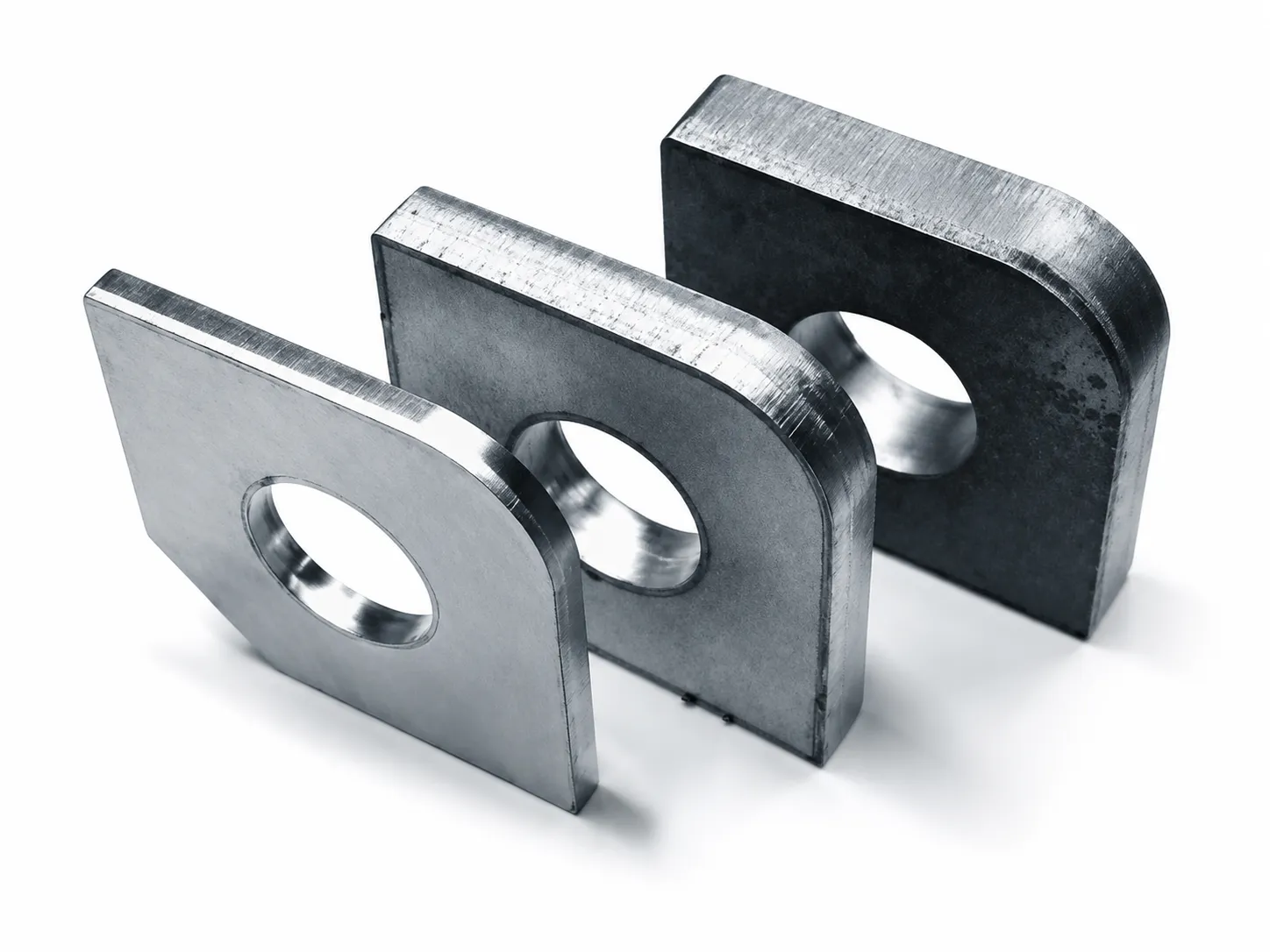
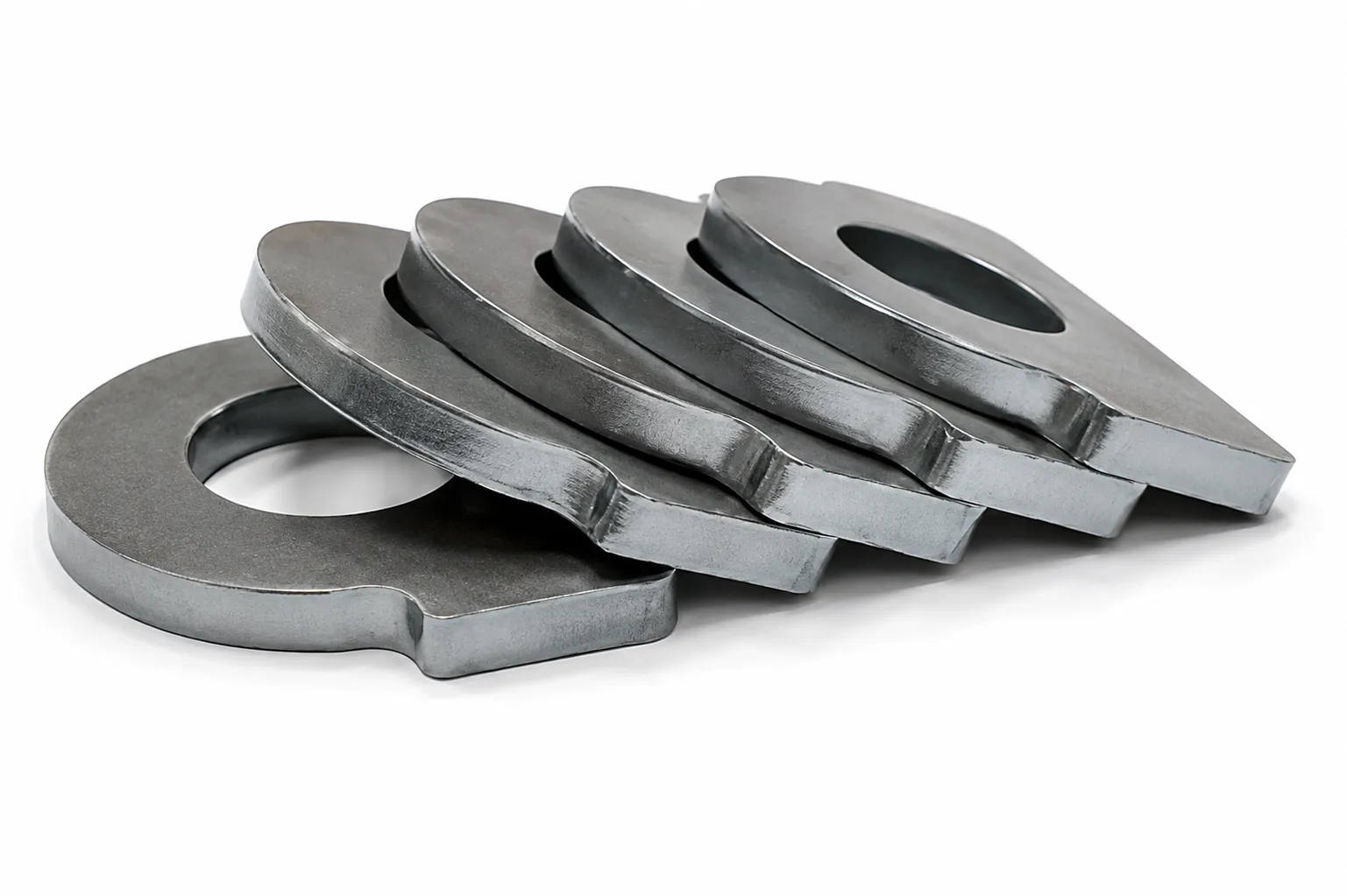
These library images are not BG test records or proof of a large-format capacity. A meaningful BG acceptance report needs the actual drawing, configuration and measured samples.
| Test item | Define before the trial |
|---|---|
| Material and machine identity | Grade/lot, measured thickness, stock condition, machine build, source/head/control and process settings. |
| Overall geometry | Length/width, relevant diagonals and datum-based feature positions using an agreed inspection method. |
| Working-area coverage | Relevant near/far or distributed locations, repeat samples and the conditions used for comparison. |
| Local cut features | Holes, slots, radii, starts, corners and edge condition, including permitted cleanup. |
| Support and recovery | Blank/part flatness, support, release, handling damage and requirements for the next operation. |
| Production route | Accepted output plus loading, cutting, sorting, finishing, inspection and rework under the same timing scope. |
State the measurement temperature/conditioning procedure where it matters to the agreed tolerance. Use the buyer's drawing and inspection plan; a public machine-axis accuracy claim is not a substitute.
Give the receiving workshop layout, doors, columns and proposed loading route. Confirm floor/foundation requirements and any on-site assembly or leveling work.
Request actual input data for the machine, source and auxiliaries, plus chiller/ambient requirements. Work area and optical power do not size the full supply.
Confirm required gas quality/flow at the machine and the proposed duct/collection arrangement. Any extraction zoning is a supplied-configuration question, not a catalogue-image inference.
Define supplied guarding, operating access, service clearances and the receiving site's installation responsibilities. An open-format image is not a laser-class or compliance certificate.
Compare the current stock/nesting route and the proposed BG route using the same order requirements. Avoid assuming that a larger blank automatically lowers material cost or that a larger nest automatically raises daily output.
Have the largest drawing and usual stock sizes?
Prepare a BG application reviewPlan access to the actual support, collection, extraction, guides and auxiliary equipment. The supplied manual should define isolation, cleaning, lubrication, inspection and calibration procedures for the delivered configuration.
Inspect supports and collection areas according to the process duty. Keep the agreed loading and service routes usable as scrap accumulates.
Follow the actual lubrication/protection procedure and retain inspection records. Review alignment checks after installation or a relevant service event.
Use specified parts and maintain gas/cooling/extraction conditions. Do not apply a fixed consumable-life schedule borrowed from another model.
Keep programs, settings and material/remnant records where supported. Confirm spare-part identification, training and service responsibilities in the agreement.
Before ordering, connect the exact BG build to the layout, application test and commercial offer. The delivery plan should identify packing/transport constraints, site preparation, assembly, commissioning and acceptance responsibilities.
List source/head/control, software licenses, auxiliaries, load and work-envelope definitions, installation drawings, sample conditions, inspection records, operator/maintenance training and manuals. State lead time, warranty/exclusions and on-site service scope in the dated agreement.
The current product preview does not establish a shipping-container size, delivery date, warranty period, local certification or service-response guarantee.
BG's catalogue identity focuses on an open large working format. High-power A discusses the laser/process package; AG discusses motion response. These characteristics can coexist, so compare the actual configuration instead of treating the names as interchangeable specifications.
Provide the largest one-piece drawing, usual purchased blanks and normal nests. Review usable travel, edge margins, support and handling restrictions with a BG-specific layout. This page does not provide a confirmed numeric size table.
No. Confirm load, support, incoming plate condition and the approved loading method as well as dimensions. A long-bed image does not establish allowable weight or point loading.
No. The part mix, stock price, permitted orientation, margins, material defects, process and useful remnants determine the result. The rectangular example only explains how extra width can help one hypothetical arrangement.
Only if the proposed machine, protection and operating method explicitly support it. Confirm included functions, zone independence and restrictions; do not assume them from the open format.
Request an application-specific acceptance plan covering datums, overall geometry, feature positions, measurement conditions and relevant work-area locations. A machine-axis figure alone cannot confirm finished-part accuracy.
Submit the material and required edge geometry. The source, head, axes, control and support must be reviewed as a complete proposed package. Large format does not itself confirm a bevel arrangement or any particular power.
Send the largest drawing and a normal nest, stock formats, grades/thicknesses, edge and inspection requirements, output, handling method and workshop layout/utilities. Mark parts that must remain one piece.
Keep the part requirements fixed while reviewing access and handling options.
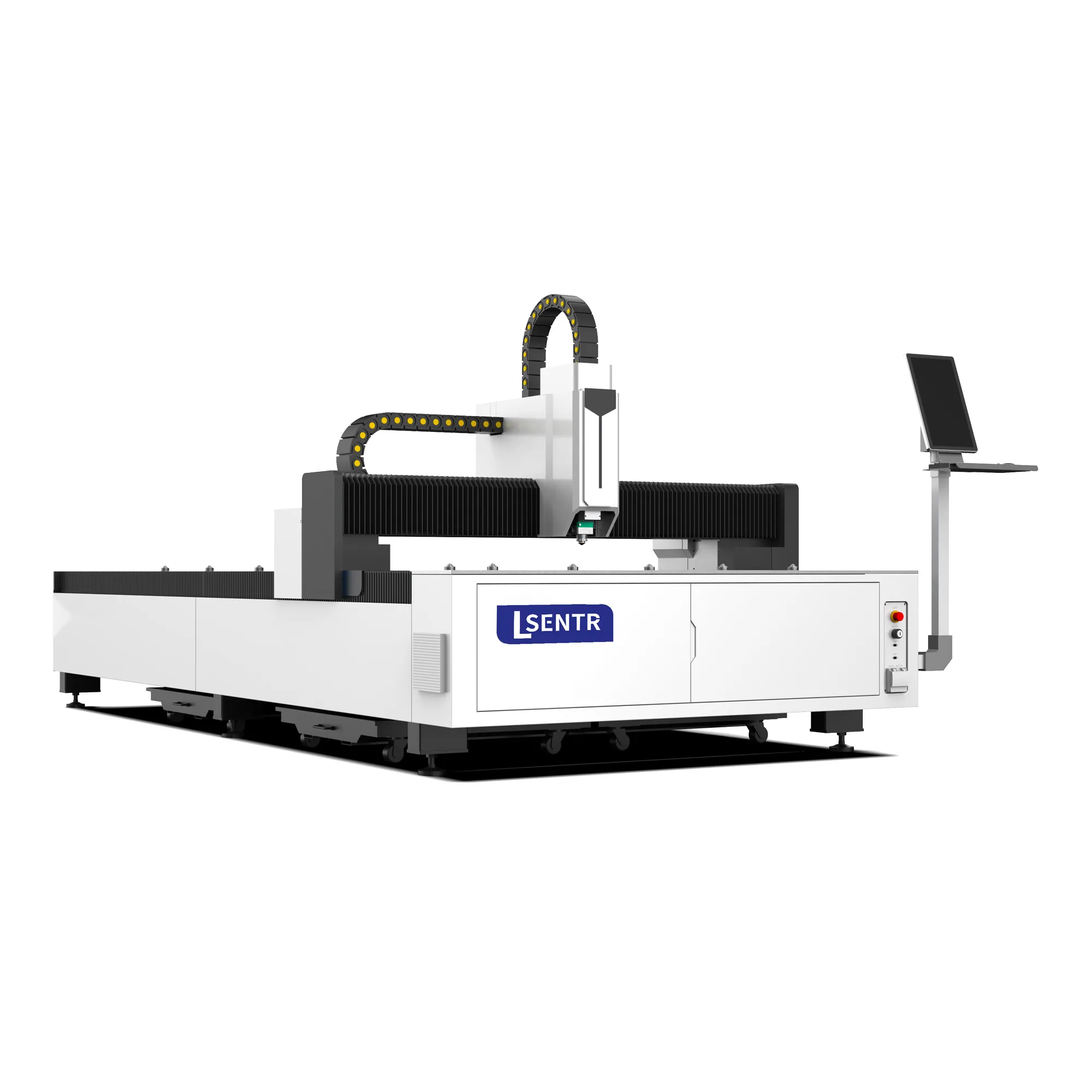
Review a standard single-table arrangement for the everyday part and stock mix.
View standard A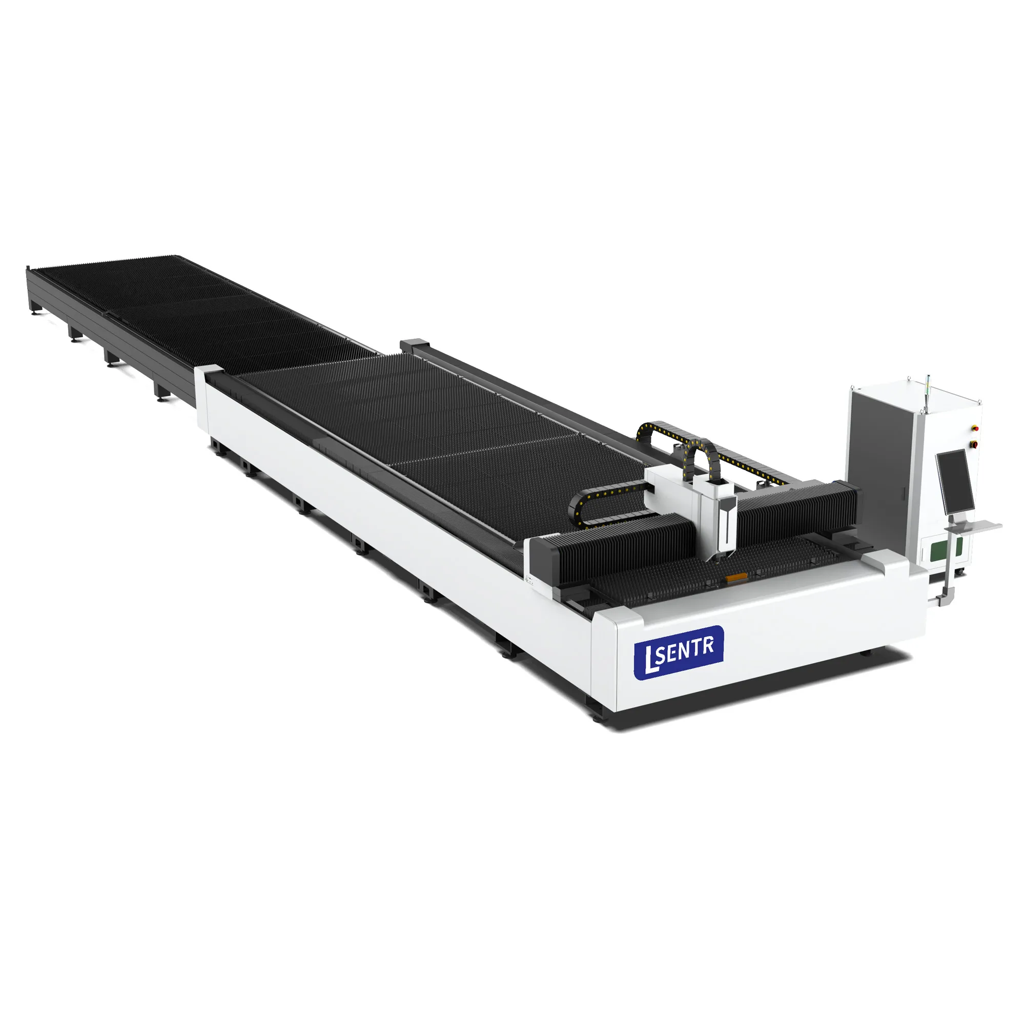
Compare outside preparation, exchange travel and the complete sheet-handling route.
View the B layout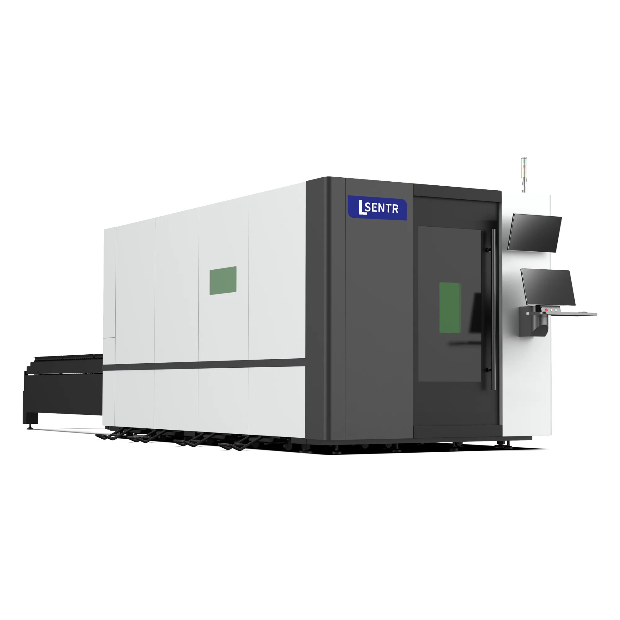
Review an enclosed cutting position, outside handling and the supplied access package.
View the BD layoutSend the largest one-piece drawing, purchased stock sizes and a normal nest. Include material, thickness, required datums and edge condition, loading/recovery method and workshop layout.
Prepare and review your requirements summary, then send it through the STR contact page or email. This form does not submit an inquiry.
Discuss your application with STR. We supply industrial laser cutting, welding, cleaning and press brake equipment for metal fabrication.
Tell STR what you need to cut. We will review the application and discuss a suitable configuration.